Subaru Legacy (2005 year). Service manual — part 500
CS-41
CONTROL SYSTEMS
MT Gear Shift Lever
11) Install the boot and the insulator assembly, and
secure them with clamp.
12) Install the front cover assembly.
13) Install the console box. <Ref. to EI-53, INSTAL-
LATION, Console Box.>
2. 6MT MODEL
1) Insert the gear shift lever from the room side.
NOTE:
Insert the rod and the stay, and then position them
onto transmission mounting.
2) Mount the cushion rubber on the body.
Tightening torque:
18 N
⋅
m (1.8 kgf-m, 13.3 ft-lb)
3) Move the transmission to the right side, then in-
stall the joint COMPL and stay.
Tightening torque:
T1: 12 N
⋅
m (1.2 kgf-m, 8.9 ft-lb)
T2: 32 N
⋅
m (3.3 kgf-m, 23.6 ft-lb)
4) Install the crossmember. <Ref. to 6MT-32, IN-
STALLATION, Transmission Mounting System.>
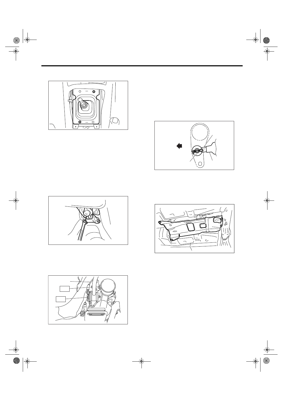
5) Install the reverse check cable end, washer and
snap pin to reverse check lever.
NOTE:
• Take care to install the snap pin in proper direc-
tion.
• Perform adjustment of reverse check cable be-
fore installation. <Ref. to CS-54, ADJUSTMENT,
Reverse Check Cable.>
6) Install the heat shield cover.
7) Install the rear exhaust pipe and muffler. <Ref. to
EX(H6DO)-7, INSTALLATION, Rear Exhaust
Pipe.> <Ref. to EX(H6DO)-9, INSTALLATION,
Muffler.>
8) Install the under cover.
9) Install the plate assembly to body.
Tightening torque:
18 N
⋅
m (1.8 kgf-m, 13.3 ft-lb)
(1) Set the plate assembly to vehicle.
(2) Temporarily tighten the bolt (A).
(3) Tighten the bolt (B).
(4) Tighten the bolt (A).
(A) Reverse check cable
CS-00312
CS-00222
CS-00223
(A)
T1
T2
(A) Reverse check cable
(B) Washer
(C) Snap pin
(D) Front side
CS-00224
(B)
(D)
(C)
(A)
AT-01331
CS-42
CONTROL SYSTEMS
MT Gear Shift Lever
(5) Tighten the bolts (C) and (D).
10) Install the harness clamp to plate.
11) Install the boot and the insulator assembly, and
secure them with clamp.
12) Install the front cover assembly.
13) Install the console box. <Ref. to EI-53, INSTAL-
LATION, Console Box.>
14) Confirm that gear shift can be shift to each gear
properly.
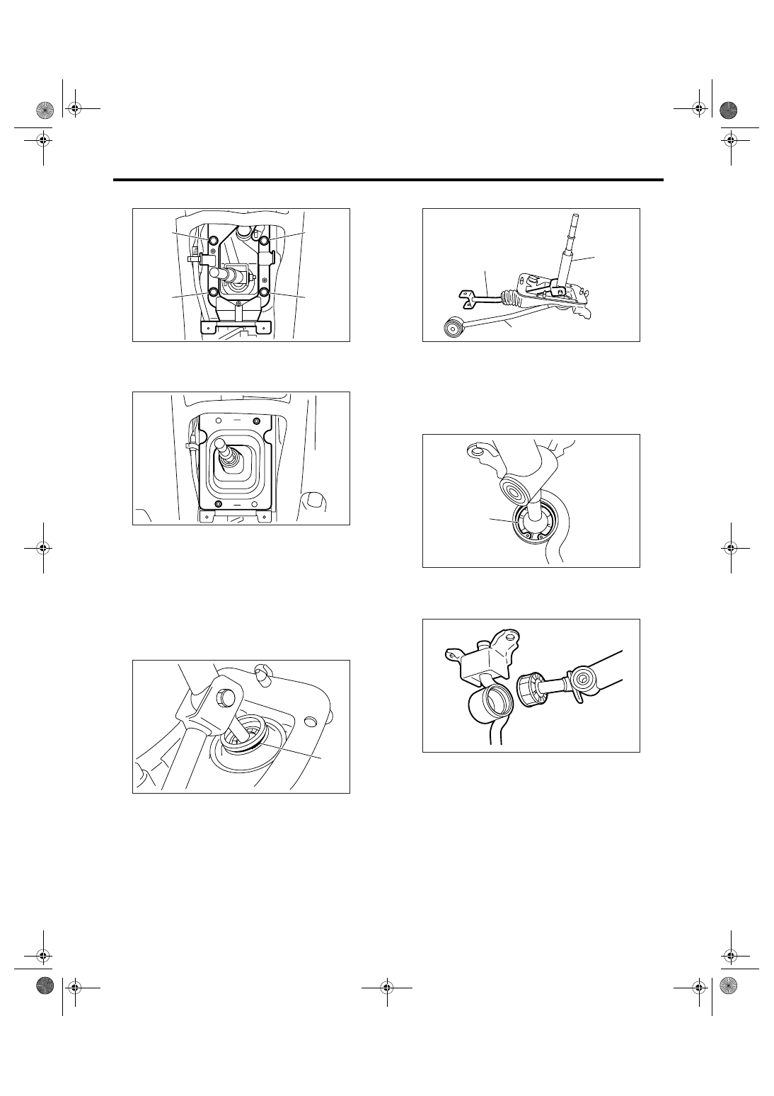
C: DISASSEMBLY
1. 5MT MODEL
1) Remove the lock wires.
2) Remove the rod from lever.
3) Separate the rod and inner boot.
4) Remove the snap ring from the stay.
5) Separate the gear shift lever and the stay.
(A) Lock wire
CS-00582
(B)
(A)
(C)
(D)
CS-00312
(A)
CS-00316
(A) Rod
(B) Lever
(C) Stay
(A) Snap ring
(A)
(B)
(C)
CS-00317
CS-00318
(A)
CS-00319
CS-43
CONTROL SYSTEMS
MT Gear Shift Lever
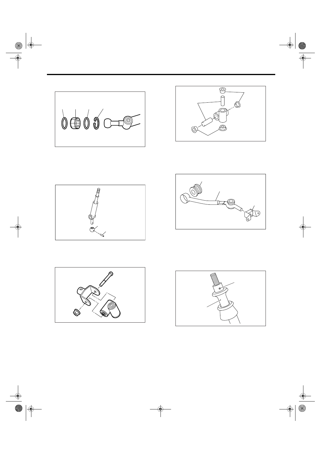
6) Remove the boot, bushing and snap ring from
gear shift lever.
7) Remove the spring pin, and then remove the
bushing and snap ring.
8) Remove the boss from the joint.
9) Remove the bushing and spacer from boss.
10) Remove the bushing and cushion rubber from
the stay.
2. 6MT MODEL
1) Remove the spring pin from the slider.
(A) O-ring
(B) Bushing
(C) Snap ring
(A) Spring pin
(B) Bushing
CS-00320
(B)
(A)
(C)
(A)
CS-00060
(B)
(A)
CS-00322
(A) Bushing
(B) Spacer
(A) Bushing B
(B) Stay
(C) Cushion rubber
(A) Slider
(B) Spring pin
CS-00238
(B)
(A)
(A)
CS-00058
(A)
(B)
(C)
CS-00225
(A)
(B)
CS-44
CONTROL SYSTEMS
MT Gear Shift Lever
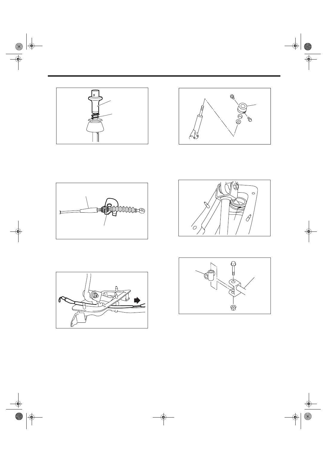
2) Remove the slider and spring.
3) Cut off the band clip
4) Remove the reverse check cable from cable
plate.
5) Remove the reverse check cable from gear shift
assembly.
6) Remove the holder and spring.
7) Disassemble the lock wires.
NOTE:
Do not reuse the lock wires.
8) Remove the boss from the rod.
(A) Slider
(B) Spring
(A) Cable plate
(B) Reverse check cable
CS-00226
(A)
(B)
CS-00228
(A)
(B)
CS-00229
(A) Holder
(A) Lock wire
(A) Rod
(B) Boss
(A)
CS-00587
CS-00231
(A)
CS-00232
(B)
(A)
Нет комментариевНе стесняйтесь поделиться с нами вашим ценным мнением.
Текст