Subaru Legacy (2005 year). Service manual — part 498
CS-33
CONTROL SYSTEMS
Shift Lock Solenoid
6. Shift Lock Solenoid
A: REMOVAL
1) Remove the console box. <Ref. to EI-53, RE-
MOVAL, Console Box.>
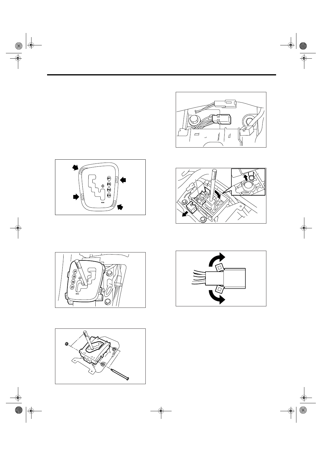
2) Remove the ring indicator.
Insert the tip of a flap tip screwdriver into the gap
between ring indicator and console front panel, and
lift up gradually.
NOTE:
• Wrap the tip of a flat tip screwdriver with cloth.
• Insert the tip of a flat tip screwdriver into four
pawls, and remove the ring indicator equally and
gradually.
3) Remove the console front panel.
4) Remove the connector.
5) Press the shift lock release button, and shift the
select lever to “N” range.
6) Remove the grip.
7) Remove the indicator cover.
8) Remove the blind.
9) Remove the bolts, and then remove the guide
plate.
10) Remove the connector from the plate assembly
using a flat-tip screwdriver.
11) Press the select lever backward while lifting up
the detent spring, and remove the shift lock sole-
noid unit.
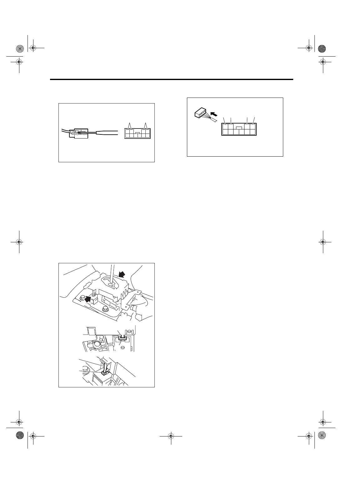
12) Raise the pawl of connector.
CS-00583
CS-00559
CS-00377
(A) Detent spring
(B) Shift lock solenoid unit
CS-00390
CS-00391
(B)
(A)
CS-00292
CS-34
CONTROL SYSTEMS
Shift Lock Solenoid
13) Disconnect the terminal of shift lock solenoid
unit from connector, using a flat-tip screwdriver with
thin tip.
B: INSTALLATION
Install in the reverse order of removal.
NOTE:
• Refer to “COMPONENT” for each tightening
torque. <Ref. to CS-3, COMPONENT, General De-
scription.>
• When installing the guide plate, shift the select
lever to “D” range (normal mode position), care
should be taken in the following points.
(1) Insert the protrusion (B) of guide plate into
the hole of shift lock solenoid unit (A).
(2) Insert the link (D) of shift lock release into
the link (C) of shift lock solenoid unit.
• Connect the switch and solenoid terminal to con-
nector.
(A) “P” range switch terminal
(B) Shift lock solenoid terminal
CS-00309
4
10
3
9 8 7
2 1
6 5
(B)
(A)
CS-00384
b
(D)
(C)
(B)
a
a
b
(A)
(A) “P” range switch (Color code: Red)
(B) “P” range switch (Color code: Red)
(C) Shift lock solenoid (Color code: Black)
(D) Shift lock solenoid (Color code: Blue and Red)
CS-00394
(D)
3
4
9 10
1
2
6
5
7
8
(C)
(B) (A)
CS-35
CONTROL SYSTEMS
Shift Lock Solenoid
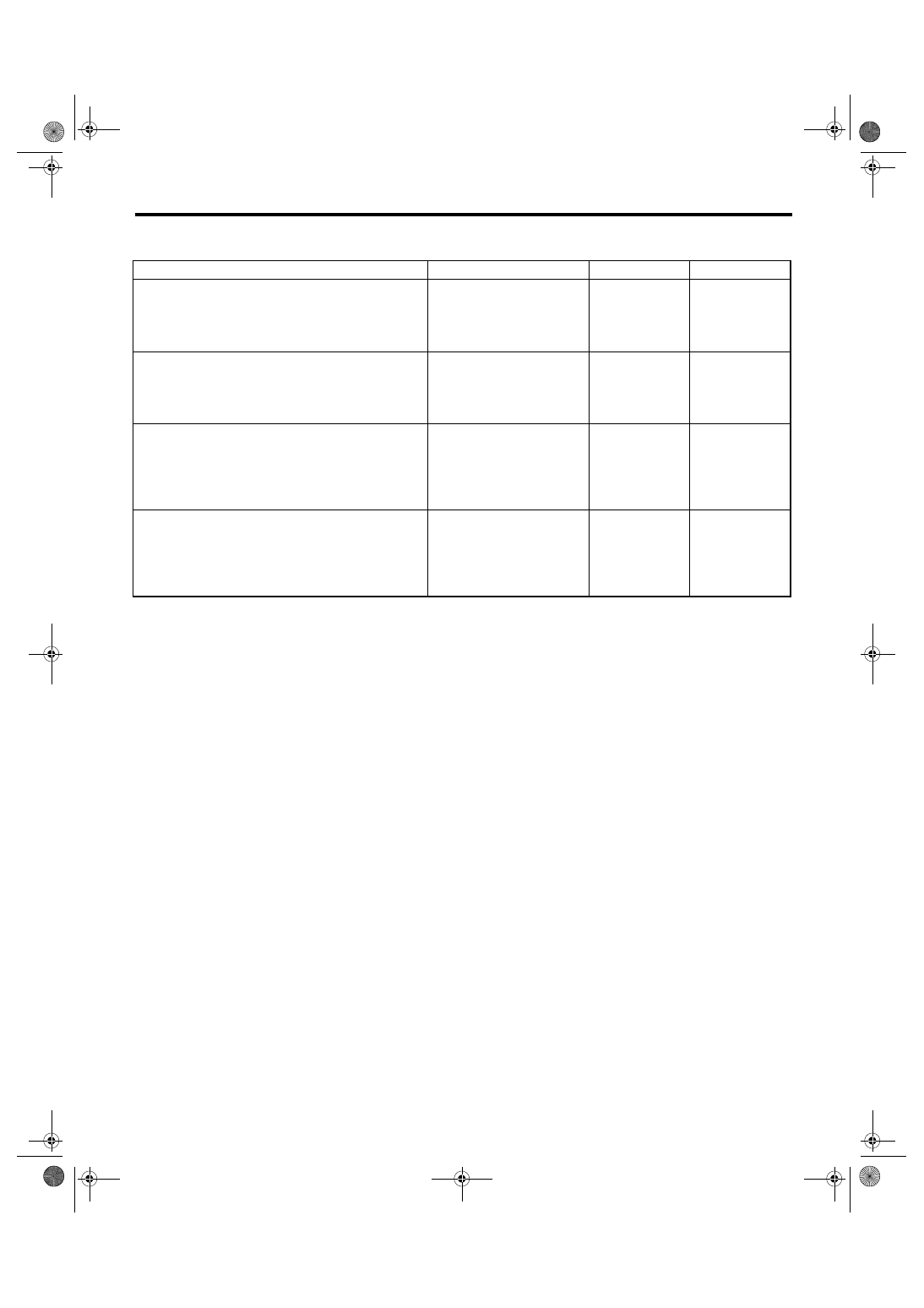
C: INSPECTION
Step
Check
Yes
No
1
CHECK SHIFT LOCK SOLENOID.
Measure the resistance of shift lock solenoid
connector terminals.
Terminal
No. 4 — No. 3:
Is the resistance 12 — 18
Ω
Replace the shift
lock solenoid.
2
CHECK SHIFT LOCK SOLENOID.
Connect the battery to shift lock solenoid con-
nector terminal, and then operate the solenoid.
Terminal
No. 3 (+) — No. 4 (
−
):
Does the shift lock solenoid
operate normally?
Replace the shift
lock solenoid.
3
CHECK “P” RANGE SWITCH.
1) Set the select lever to “P” range.
2) Measure the resistance between “P” range
switch connector terminals.
Terminal
No. 1 — No. 2:
Is the resistance less than 1
Ω?
Replace the “P”
range switch.
4
CHECK “P” RANGE SWITCH.
1) Set the select lever to other than “P” range.
2) Measure the resistance between “P” range
switch connector terminals.
Terminal
No. 1 — No. 2:
Is the resistance more than 1
M
Ω?
Normal
Replace the “P”
range switch.
CS-36
CONTROL SYSTEMS
Body Integrated Module
7. Body Integrated Module
A: NOTE
Refer to “Body Integrated Module” for removal and
installation procedure. <Ref. to SL-44, Body Inte-
grated Module.>
Нет комментариевНе стесняйтесь поделиться с нами вашим ценным мнением.
Текст