Subaru Legacy (2005 year). Service manual — part 499
CS-37
CONTROL SYSTEMS
MT Gear Shift Lever
8. MT Gear Shift Lever
A: REMOVAL
1. 5MT MODEL
1) Set the vehicle on a lift.
2) Disconnect the ground cable from battery.
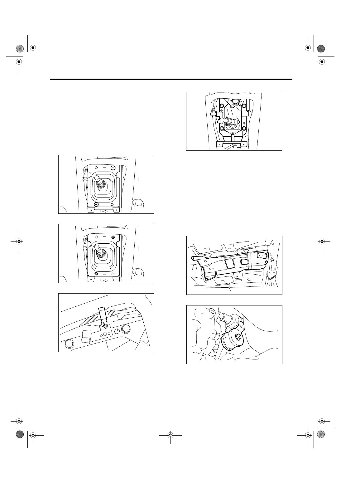
3) Remove the gear shift knob.
4) Remove the console box. <Ref. to EI-53, RE-
MOVAL, Console Box.>
5) Remove the front cover assembly.
6) Remove the clamp.
7) Remove the boot and insulator assembly.
8) Remove the harness clamp from plate.
9) Remove the plate assembly from vehicle body.
10) Lift-up the vehicle.
11) Remove the rear exhaust pipe and muffler.
• SOHC model
<Ref. to EX(H4SO 2.0)-10, REMOVAL, Rear Ex-
haust Pipe.> <Ref. to EX(H4SO 2.0)-12, REMOV-
AL, Muffler.>
• DOHC non-turbo model
<Ref. to EX(H6DO)-7, REMOVAL, Rear Exhaust
Pipe.> <Ref. to EX(H6DO)-9, REMOVAL, Muffler.>
• DOHC turbo model
<Ref. to EX(H4DOTC)-11, REMOVAL, Rear Ex-
haust Pipe.> <Ref. to EX(H4DOTC)-10, REMOV-
AL, Joint Pipe.>
12) Remove the heat shield cover.
13) Remove the stay from transmission bracket.
CS-00311
CS-00312
CS-00313
(A) Stay
(B) Transmission bracket
CS-00563
AT-01331
CS-00050
(A)
(B)
CS-38
CONTROL SYSTEMS
MT Gear Shift Lever
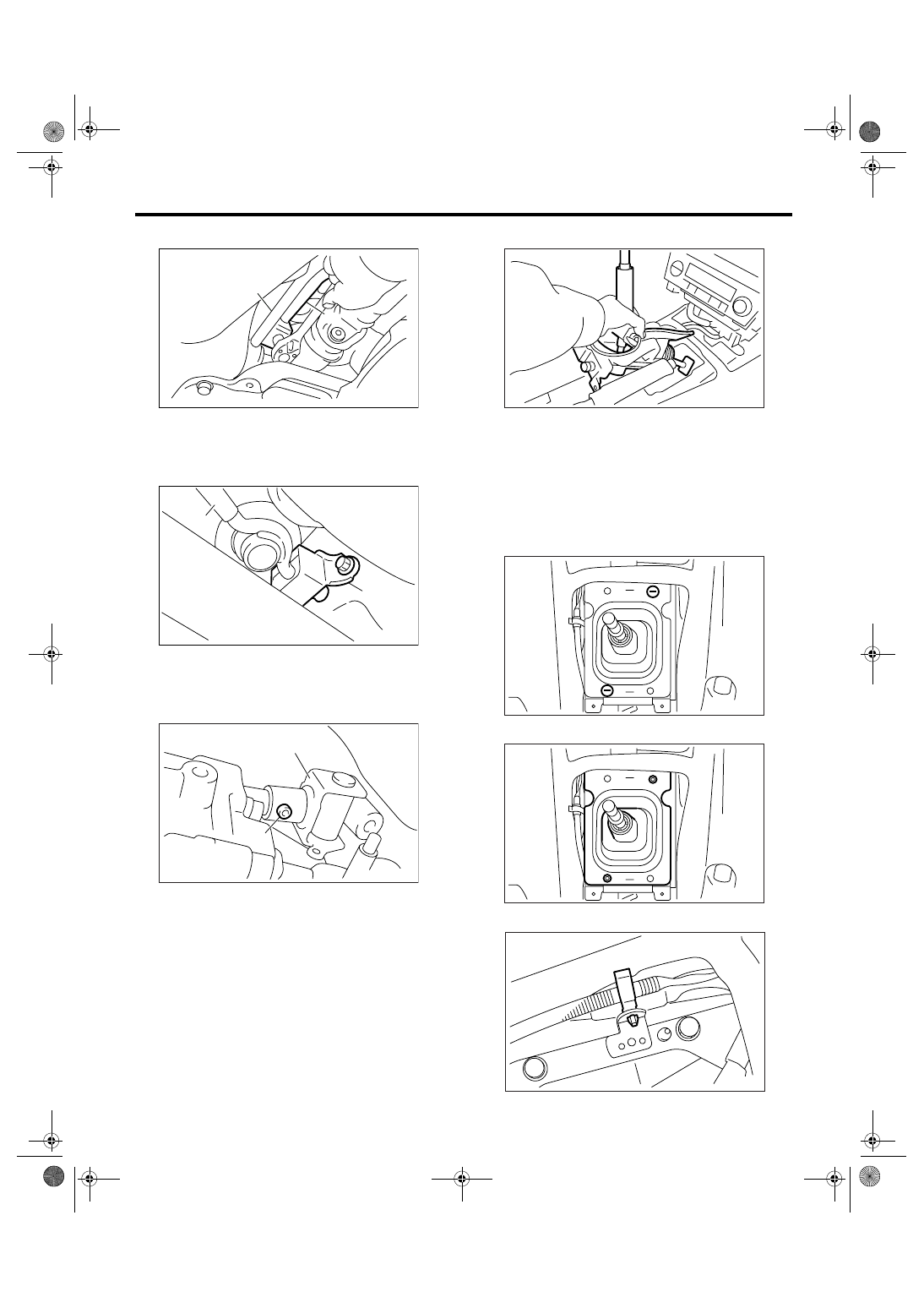
14) Remove the rod from joint.
15) Remove the cushion rubber from vehicle body.
16) Extract the spring pin and remove the joint.
17) Lower the vehicle.
18) Remove the gear shift lever.
2. 6MT MODEL
1) Lift-up the vehicle.
2) Disconnect the ground cable from battery.
3) Remove the gear shift knob.
4) Remove the console box front. <Ref. to EI-53,
REMOVAL, Console Box.>
5) Remove the front cover assembly.
6) Remove the clamp.
7) Remove the boot and insulator assembly.
8) Remove the harness clamp from plate.
(A) Stay
(B) Rod
(A) Stay
(B) Cushion rubber
(A) Joint
(B) Spring pin
CS-00051
(A)
(B)
CS-00052
(A)
(B)
CS-00053
(A)
(B)
CS-00315
CS-00311
CS-00312
CS-00581
CS-39
CONTROL SYSTEMS
MT Gear Shift Lever
9) Remove the plate assembly from vehicle body.
10) Lift-up the vehicle.
11) Remove the under cover.
12) Remove the rear exhaust pipe and muffler.
<Ref. to EX(H6DO)-7, REMOVAL, Rear Exhaust
Pipe.> <Ref. to EX(H6DO)-9, REMOVAL, Muffler.>
13) Remove the heat shield cover.
14) Remove the crossmember. <Ref. to 6MT-32,
REMOVAL, Transmission Mounting System.>
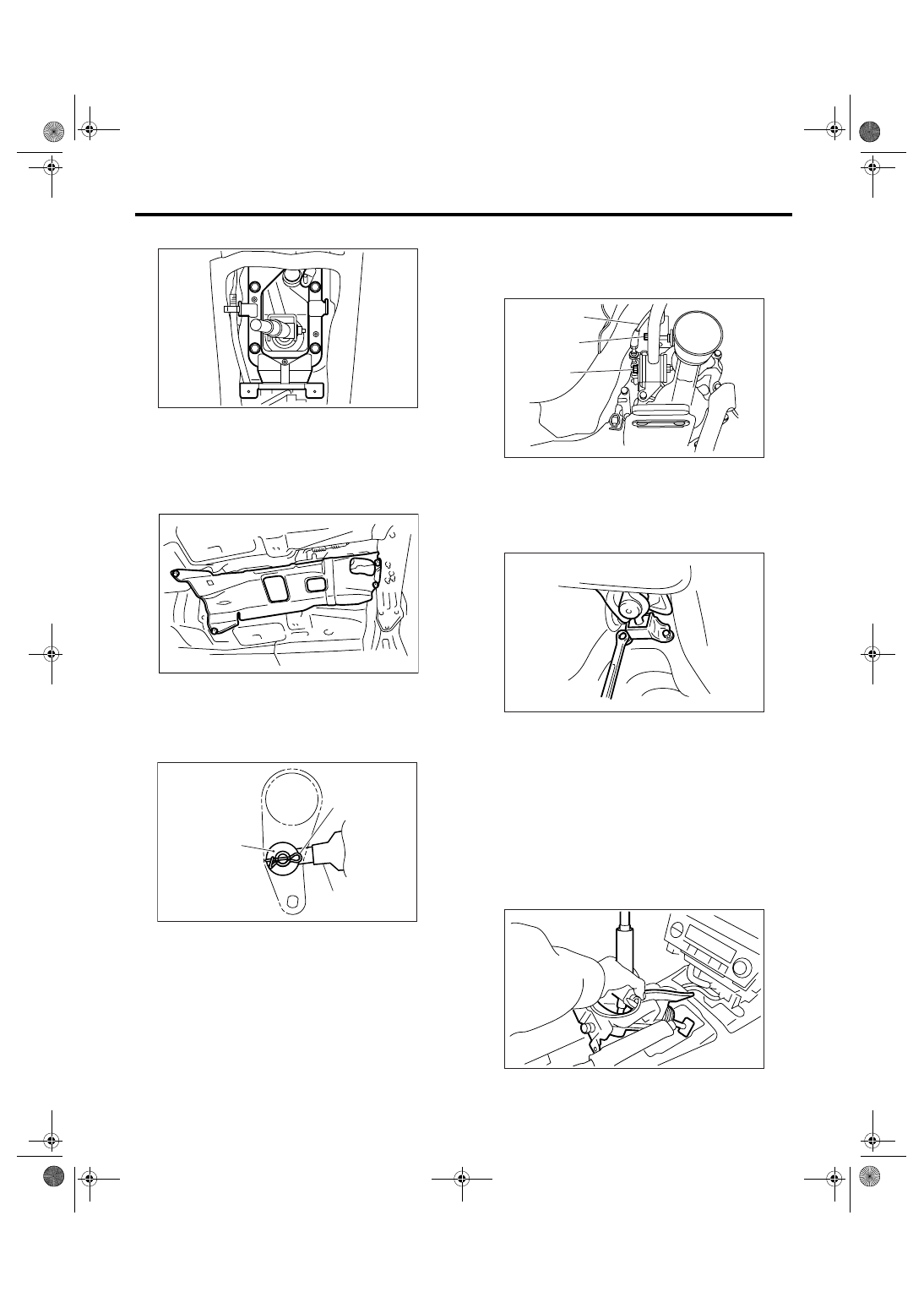
15) Remove the snap pin and washer, and then re-
move the reverse check cable from reverse check
lever.
16) Move the transmission to the right side, then re-
move the joint COMPL, stay bolt and reverse check
cable.
NOTE:
If the transmission is not moved, joint COMPL and
stay bolt may contact the body. It will cause dam-
age.
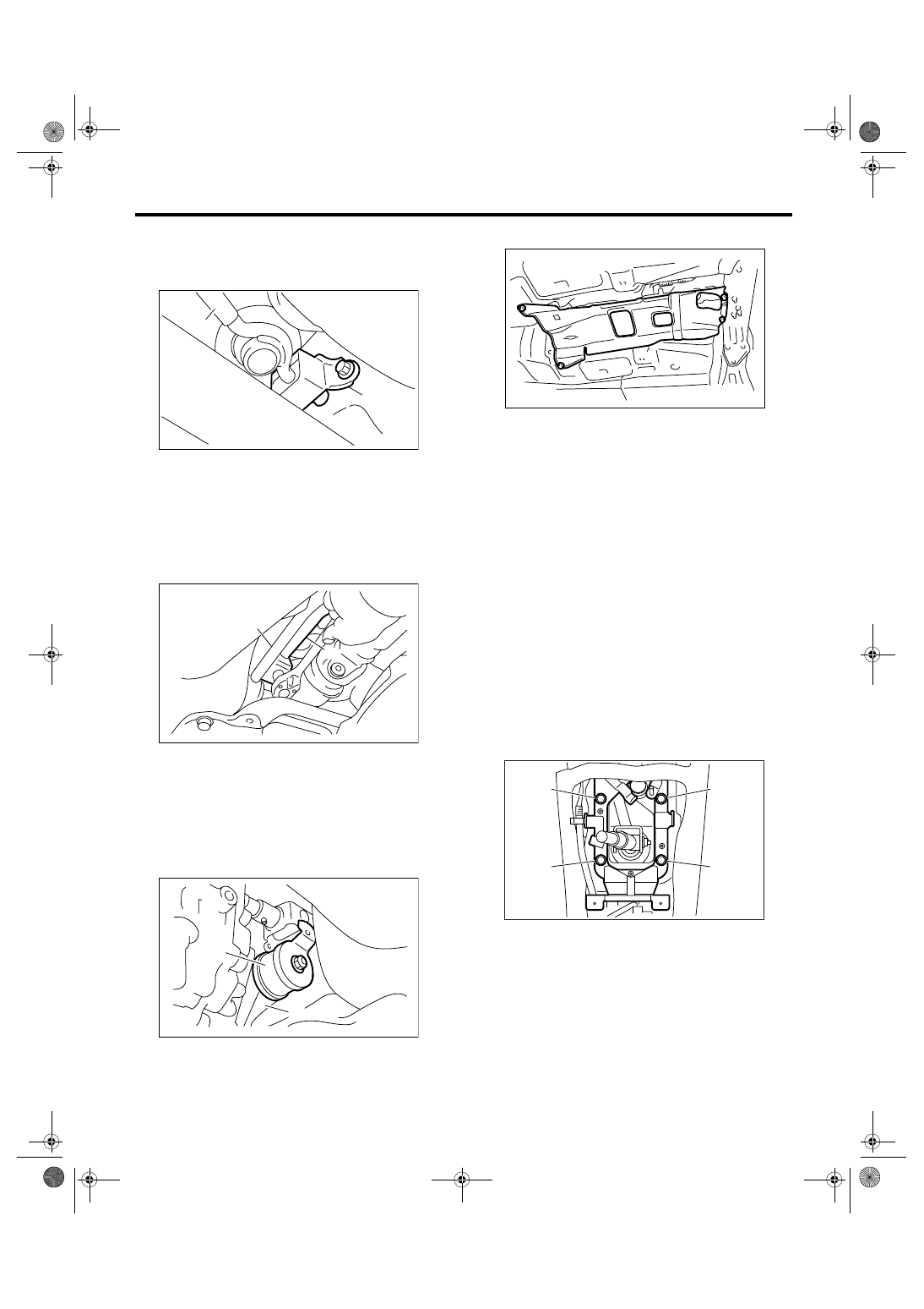
17) Remove the cushion rubber from body.
18) Lower the vehicle.
19) Remove the gear shift lever.
B: INSTALLATION
1. 5MT MODEL
1) Install the joint to transmission and secure with
spring pin.
2) Insert the gear shift lever from the room side.
NOTE:
Insert the rod and the stay, and then temporarily set
them onto transmission mounting.
3) Lift-up the vehicle.
(A) Snap pin
(B) Washer
(C) Reverse check cable
CS-00584
AT-01331
CS-00220
(B)
(A)
(C)
(A) Joint COMPL bolt
(B) Stay bolt
(C) Reverse check cable
CS-00221
(C)
(A)
(B)
CS-00222
CS-00315
CS-40
CONTROL SYSTEMS
MT Gear Shift Lever
4) Mount the cushion rubber on the vehicle body.
Tightening torque:
18 N
⋅
m (1.8 kgf-m, 13.3 ft-lb)
5) Using new self-locking nuts, connect the rod to
the joint.
Tightening torque:
18 N
⋅
m (1.8 kgf-m, 13.3 ft-lb)
6) Using new self-locking nuts, connect the stay to
transmission bracket.
Tightening torque:
18 N
⋅
m (1.8 kgf-m, 13.3 ft-lb)
7) Install the heat shield cover.
8) Install the rear exhaust pipe and muffler.
• SOHC model
<Ref. to EX(H4SO 2.0)-10, INSTALLATION, Rear
Exhaust Pipe.> <Ref. to EX(H4SO 2.0)-12, IN-
STALLATION, Muffler.>
• DOHC non-turbo model
<Ref. to EX(H6DO)-7, INSTALLATION, Rear Ex-
haust Pipe.> <Ref. to EX(H6DO)-9, INSTALLA-
TION, Muffler.>
• DOHC turbo model
<Ref. to EX(H4DOTC)-11, INSTALLATION, Rear
Exhaust Pipe.> <Ref. to EX(H4DOTC)-12, IN-
STALLATION, Muffler.>
9) Install the plate assembly to body.
Tightening torque:
18 N
⋅
m (1.8 kgf-m, 13.3 ft-lb)
(1) Set the plate assembly to vehicle.
(2) Temporarily tighten the bolt (A).
(3) Tighten the bolt (B).
(4) Tighten the bolt (A).
(5) Tighten the bolts (C) and (D).
10) Install the harness clamp to plate.
(A) Stay
(B) Cushion rubber
(A) Stay
(B) Rod
(A) Stay
(B) Transmission bracket
CS-00052
(A)
(B)
CS-00051
(A)
(B)
CS-00050
(A)
(B)
AT-01331
CS-00314
(B)
(A)
(C)
(D)
Нет комментариевНе стесняйтесь поделиться с нами вашим ценным мнением.
Текст