Subaru Legacy (2005 year). Service manual — part 1037
LAN(diag)-27
LAN SYSTEM (DIAGNOSTICS)
Function Setting (Customize)
10.Function Setting (Customize)
A: OPERATION
1. WITHOUT SUBARU SELECT MONITOR
NOTE:
Applied to the Model with center display.
1) Display the information screen with pressing the
“INFO” switch of center display.
2) Select “SET” on the touch panel at the right top
of center display screen.
3) Select the item from “A: Keyless entry” or “B:
Various setup” on the touch panel.
4) Change the setting on the touch panel which
contains item to be changed.
5) Return to the information display screen and
complete it.
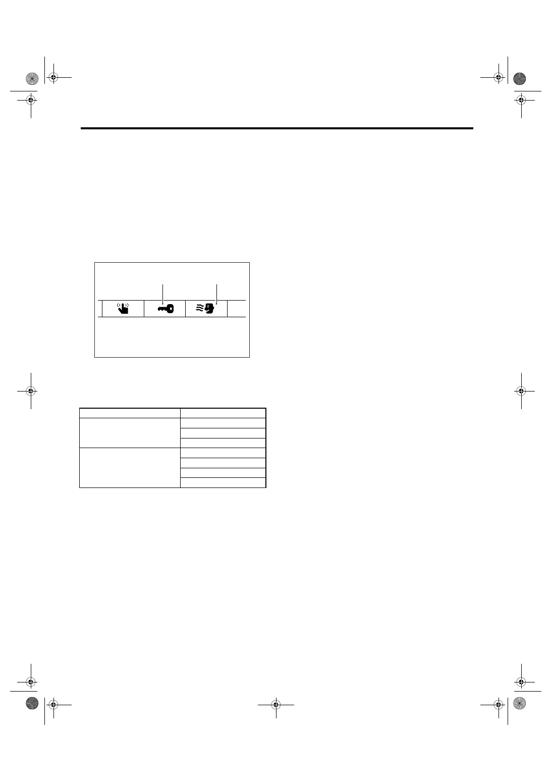
Function setting item list
2. WITH SUBARU SELECT MONITOR
For detailed procedures of function setting (ECM
customizing), refer to “SUBARU SELECT MONI-
TOR”. <Ref. to LAN(diag)-21, FUNCTION SET-
TING (ECM CUSTOMIZING), OPERATION,
Subaru Select Monitor.>
Item
Setting
Keyless
Auto lock
Auto lock time setting
Answerback hazard
Each function
Room light delay time
Anti-lock out
Rear defogger
Wiper deicer
(B)
(A)
LAN00112

LAN(diag)-28
LAN SYSTEM (DIAGNOSTICS)
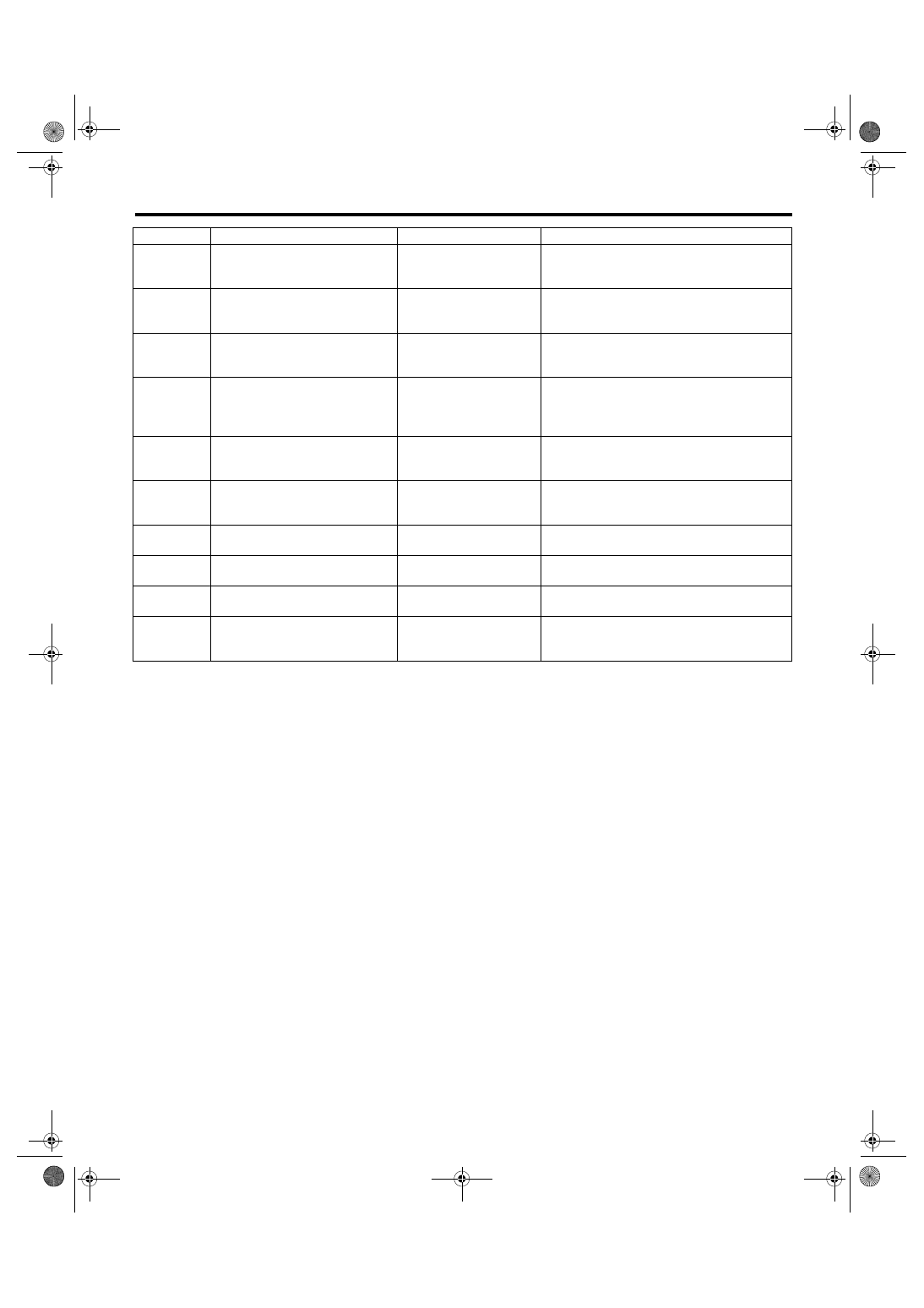
List of Diagnostic Trouble Code (DTC)
11.List of Diagnostic Trouble Code (DTC)
A: LIST
DTC
Item
Contents of diagnosis
NOTE
None
Communication for initializing
impossible
Open or short in Subaru
Select Monitor communi-
cation line
None
Diagnostic Trouble Code (DTC) is
not stored.
Internal error of combina-
tion meter
B0100
Integ. unit system error
Body integrated module
internal error
B0101
BATT p/supply malfunction cont.
Open or short in battery
power supply control cir-
cuit
B0102
BATT p/supply malfunction cont.
Open or short in battery
power backup circuit
B0103
Ignition power failure
Open or short in IGN
power supply circuit
B0104
ACC power failure
Open or short in ACC
power supply circuit
B0106
Shift lock circuit failure
Ground short of shift lock
circuit
B0107
R fog lamp circuit failure
Ground short of rear fog
circuit
B0201
CAN-HS counter abnormal
Malfunction of high-speed
CAN communication
B0202
CAN-HS bus off
Any unit is cut communi-
cation.
B0211
CAN-HS ECM data abnormal
Received error data from
ECM.
B0212
CAN-HS TCM data abnormal
Received error data from
TCM.
B0213
CAN-HS VDC/ABS data abnormal
Received error data from
VDC/ABS unit.
B0221
CAN-HS ECM no-receive data
Not received error data
from ECM.
B0222
CAN-HS TCM no-receive data
Not received error data
from TCM.
B0223
CAN-HS VDC/ABS no-receive
data
Not received error data
from VDC/ABS unit.
LAN(diag)-29
LAN SYSTEM (DIAGNOSTICS)
List of Diagnostic Trouble Code (DTC)
B0300
CAN-LS malfunction
Open or short in low-
speed CAN circuit, on
each side or both sides.
B0301
CAN-LS counter abnormal
Malfunction of low-speed
CAN communication
B0302
CAN-LS bus off
Any unit is cut communi-
cation.
B0311
CAN-LS meter unit data abnormal
Received error data from
meter.
B0313
CAN-LS monitor data abnormal
Received error data from
monitor unit.
B0321
CAN-LS meter no-receive data
Not received error data
from meter.
B0401
M collation NG
Malfunction related immo-
bilizer
<Ref. to IM(diag)-15, List of Diagnostic Trouble
Code (DTC).>
B0402
Immobilizer Key collation NG
Malfunction related immo-
bilizer
<Ref. to IM(diag)-15, List of Diagnostic Trouble
Code (DTC).>
B0403
E/G request NG
Malfunction related immo-
bilizer
<Ref. to IM(diag)-15, List of Diagnostic Trouble
Code (DTC).>
B0500
Keyless UART com. malfunction
Open or short circuit in
keyless UART circuit
DTC
Item
Contents of diagnosis
NOTE
LAN(diag)-30
LAN SYSTEM (DIAGNOSTICS)
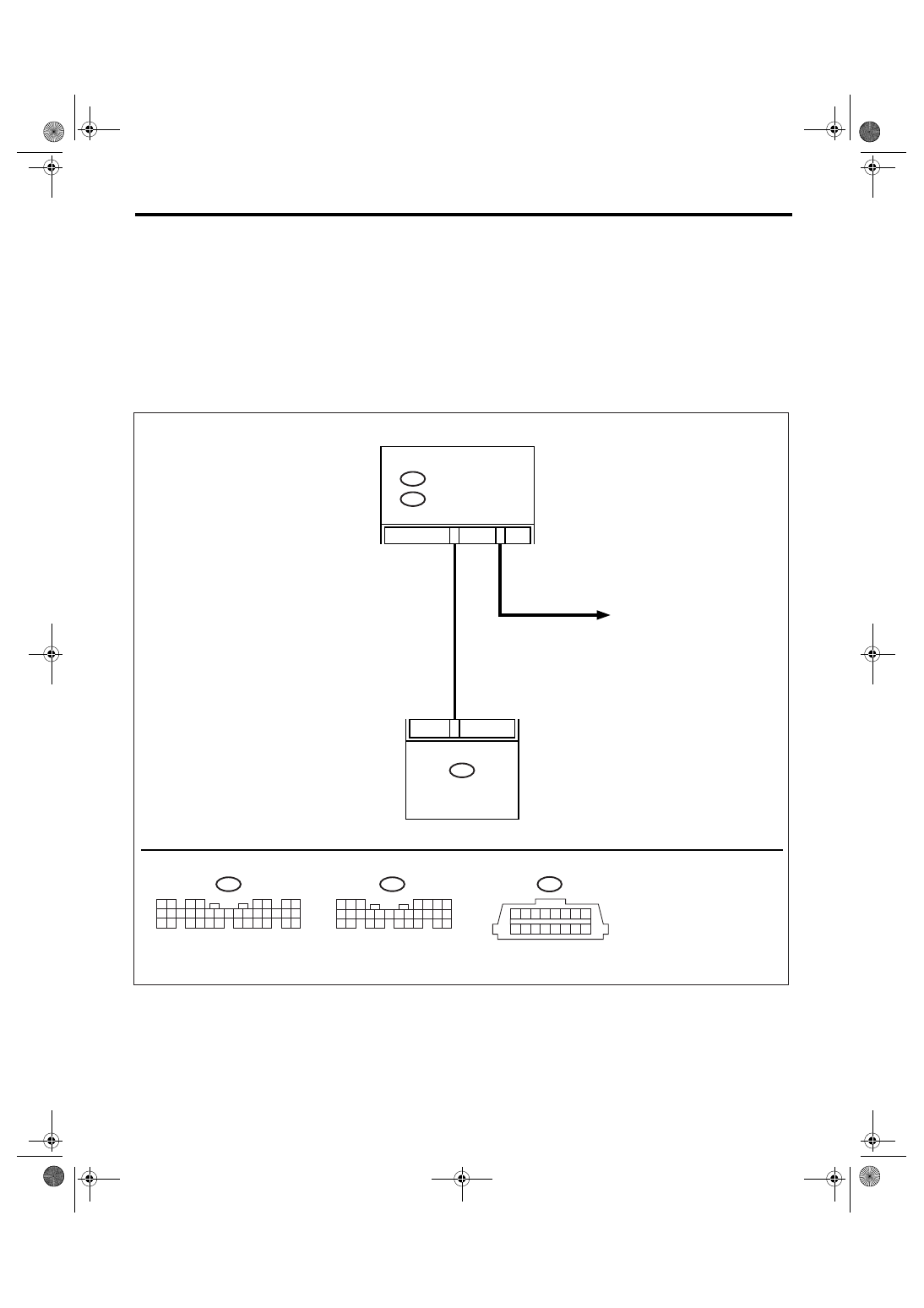
Diagnostic Procedure with Diagnostic Trouble Code (DTC)
12.Diagnostic Procedure with Diagnostic Trouble Code (DTC)
A: COMMUNICATION FOR INITIALIZING IMPOSSIBLE
NOTE:
• DTC is displayed in the sequence of the amount of counter numbers.
• When more than two DTCs are displayed, perform the diagnosis of top of them.
DIAGNOSIS:
Subaru Select Monitor communication line is open or shorted.
TROUBLE SYMPTOM:
Not communicable with Subaru Select Monitor.
WIRING DIAGRAM:
10
A1
B19
1 2 3 4 5 6 7 8
9 10 11 12 13 14 15 16
B40
i84
A:
B280
B:
B40
i84
A:
B280
B:
LAN00166
5 6 7
8
2
1
9
4
3
10
24
22 23
25
11 12 13 14 15
26
27 28
16 17 18 19
20 21
1 2
3 4
5 6
7 8
9 10 11 12 13 14 15 16 17 18 19 20 21 22 23
24 25
26 27 28 29
30 31 32 33
34 35
BODY
INTEGRATED
MODULE
IGNITION RELAY
DATA LINK CONNECTOR
Нет комментариевНе стесняйтесь поделиться с нами вашим ценным мнением.
Текст