Subaru Legacy (2005 year). Service manual — part 688
6MT-99
MANUAL TRANSMISSION AND DIFFERENTIAL
Drive Pinion Shaft Assembly
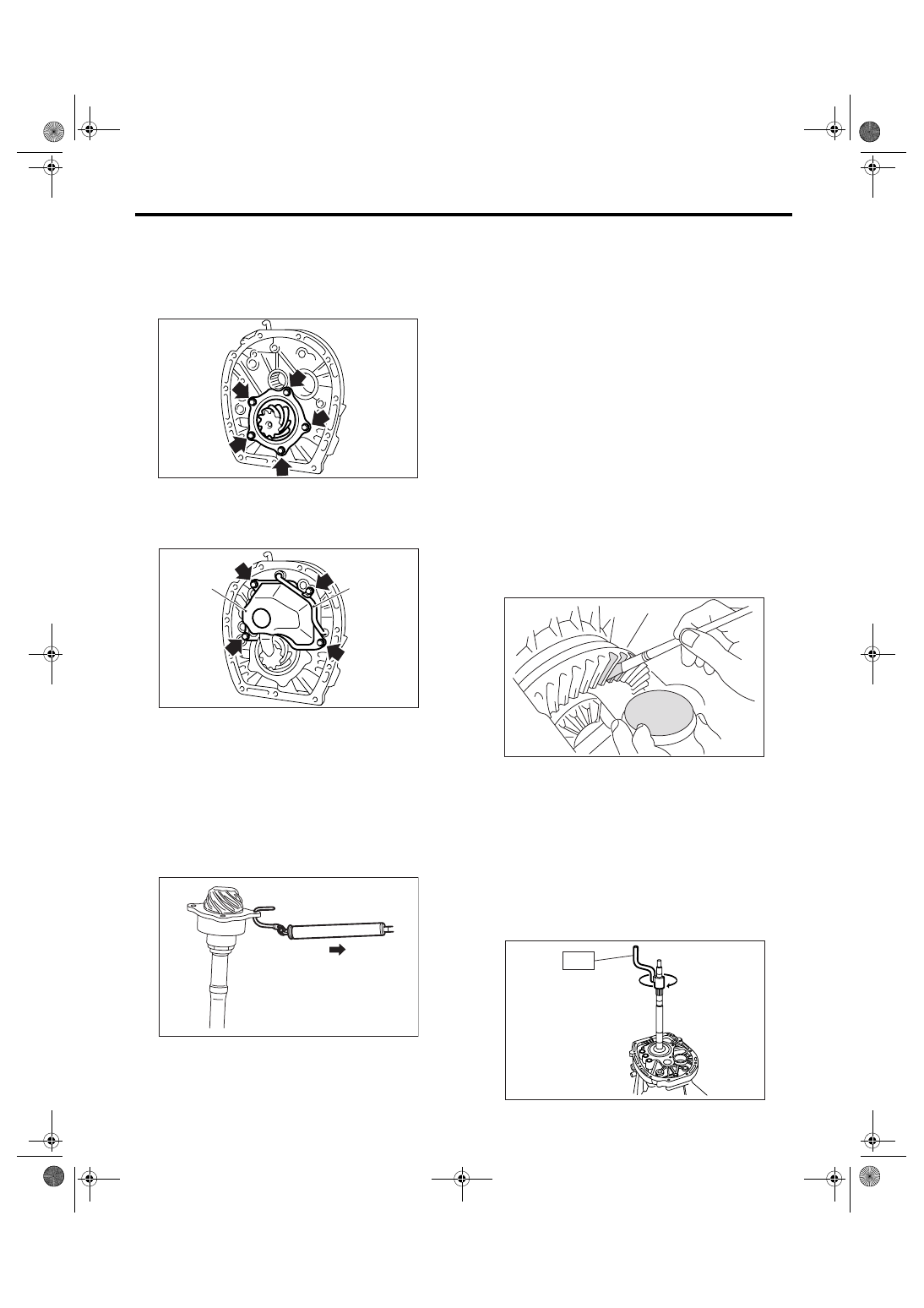
10) Apply gear oil to the side face of taper roller
bearing, then install the drive pinion shaft and se-
lected shim to adapter plate.
Tightening torque:
54 N
⋅
m (5.5 kgf-m, 40 ft-lb)
11) Install the oil chamber and pipe.
Tightening torque:
6.4 N
⋅
m (0.65 kgf-m, 4.7 ft-lb)
E: INSPECTION
1) Using the spring balance, measure the starting
torque. If the starting torque is out of specification,
replace the taper roller bearing.
Starting torque:
0 — 0.95 N (0 — 0.097 kgf, 0 — 0.21 lbf)
2) Gear
Replace the gear in the following cases.
• When the gear teeth surfaces are broken or ex-
cessively worn.
3) Bearing
Replace the bearings in the following cases.
• When there are wear, rust and damage on the
bearing.
• When bearing that fails to turn smoothly or
makes noise when turned.
4) Adapter plate
Replace the adapter plate in the following cases.
• When the bearing is worn, rusted and damaged.
• When there is damage on adapter plate.
5) Make sure the pipe and pipe chamber is not
damaged or clogged. Repair or replace if damaged
or clogged.
F: ADJUSTMENT
1) Inspect and adjust the backlash between hypoid
driven gear and drive pinion. <Ref. to 6MT-108,
HYPOID GEAR BACKLASH, ADJUSTMENT,
Front Differential Assembly.>
2) Apply a uniform thin coat of red lead on both
tooth surfaces of three or four teeth of the hypoid
driven gear.
3) Install the drive pinion shaft assembly to clutch
housing, then tighten at least four bolts.
NOTE:
Install with the liquid gasket remaining to prevent
the mating surface of clutch housing and adapter
plate from damaging.
Tightening torque:
50 N
⋅
m (5.1 kgf-m, 36.9 ft-lb)
4) Using the ST, rotate several times.
ST
18631AA000
HANDLE
(A) Pipe
(B) Oil chamber
MT-00642
(A)
(B)
MT-00641
MT-00651
MT-00652
MT-00653
ST
6MT-100
MANUAL TRANSMISSION AND DIFFERENTIAL
Drive Pinion Shaft Assembly
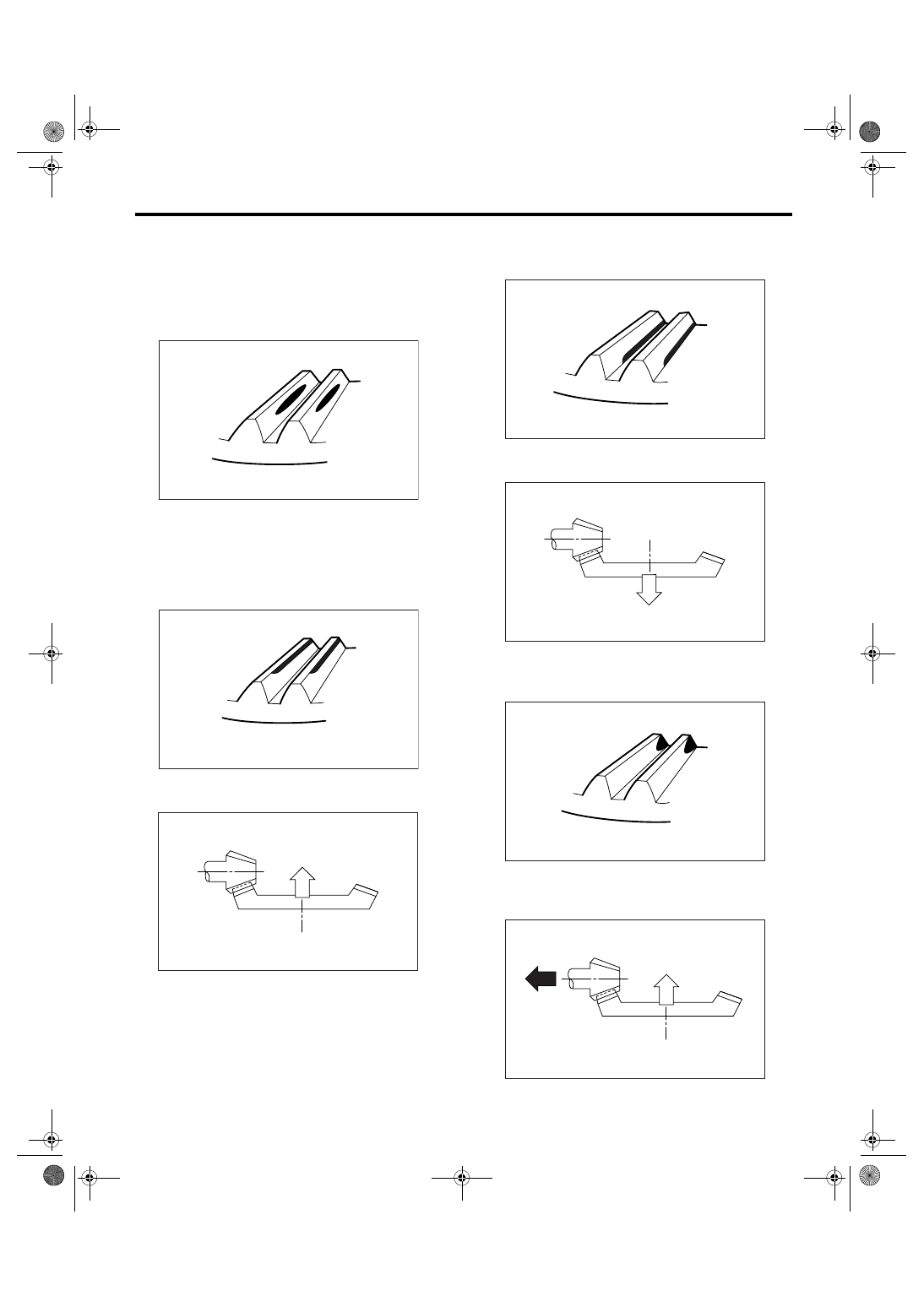
5) Remove the drive pinion shaft assembly, and
then check tooth contact. If it is not normal, adjust
the backlash or thickness of shim.
• Tooth contact
Checking item: Tooth contact pattern is slightly
shifted to toe side under no-load rotation.
(When loaded, it moves toward heel side.)
• Face contact
Checking item: Backlash is excessive.
Contact pattern
Adjustment: Check the backlash again and adjust
it.
• Flank contact
Checking item: Backlash is too small.
Contact pattern
Adjustment: Check the backlash again and adjust
it.
• Toe contact (inside end contact)
Checking item: Contact area is small.
Contact pattern
Adjustment: Reduce thickness of drive pinion shim
according to the procedure for bringing drive pinion
away from driven gear.
(A) Toe side
(B) Heel side
AT-00207
(A)
(B)
AT-00208
AT-01253
AT-00209
AT-01254
AT-00210
AT-00213
6MT-101
MANUAL TRANSMISSION AND DIFFERENTIAL
Drive Pinion Shaft Assembly
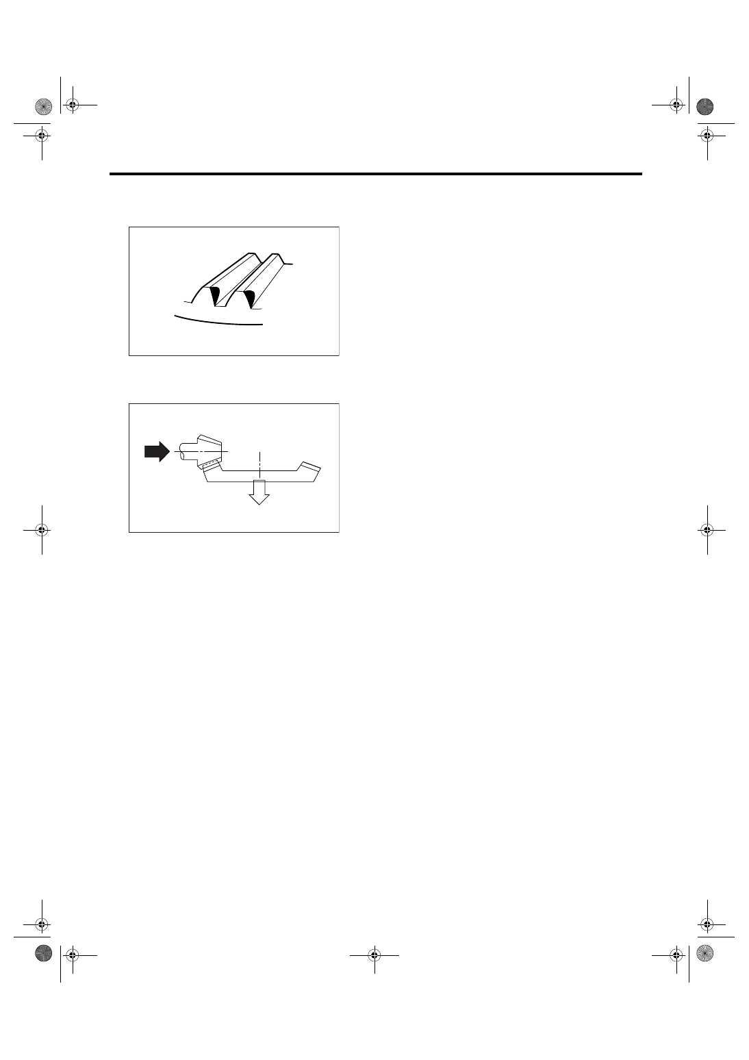
• Heel contact (outside end contact)
Checking item: Contact area is small.
Contact pattern
Adjustment: Increase thickness of drive pinion ac-
cording to procedure for moving drive pinion closer
to driven gear side.
AT-00211
AT-00212
6MT-102
MANUAL TRANSMISSION AND DIFFERENTIAL
Front Differential Assembly
23.Front Differential Assembly
A: REMOVAL
1) Remove the manual transmission assembly
from vehicle. <Ref. to 6MT-34, REMOVAL, Manual
Transmission Assembly.>
2) Prepare the transmission for overhaul. <Ref. to
6MT-40, Preparation for Overhaul.>
3) Remove the oil pipe, neutral position switch,
back-up light switch and harness. <Ref. to 6MT-42,
REMOVAL, Oil Pipe.> <Ref. to 6MT-45, REMOV-
AL, Neutral Position Switch.> <Ref. to 6MT-43, RE-
MOVAL, Back-up Light Switch.>
4) Remove the extension case. <Ref. to 6MT-47,
REMOVAL, Extension Case.>
5) Remove the transfer driven gear. <Ref. to 6MT-
58, REMOVAL, Transfer Driven Gear.>
6) Remove the center differential. <Ref. to 6MT-60,
REMOVAL, Center Differential.>
7) Remove the oil pump. <Ref. to 6MT-61, RE-
MOVAL, Oil Pump.>
8) Remove the transmission case. <Ref. to 6MT-
64, REMOVAL, Transmission Case.>
9) Remove each gear assembly. <Ref. to 6MT-69,
REMOVAL, Main Shaft Assembly.>
10) Remove the drive pinion shaft assembly. <Ref.
to 6MT-96, REMOVAL, Drive Pinion Shaft Assem-
bly.>
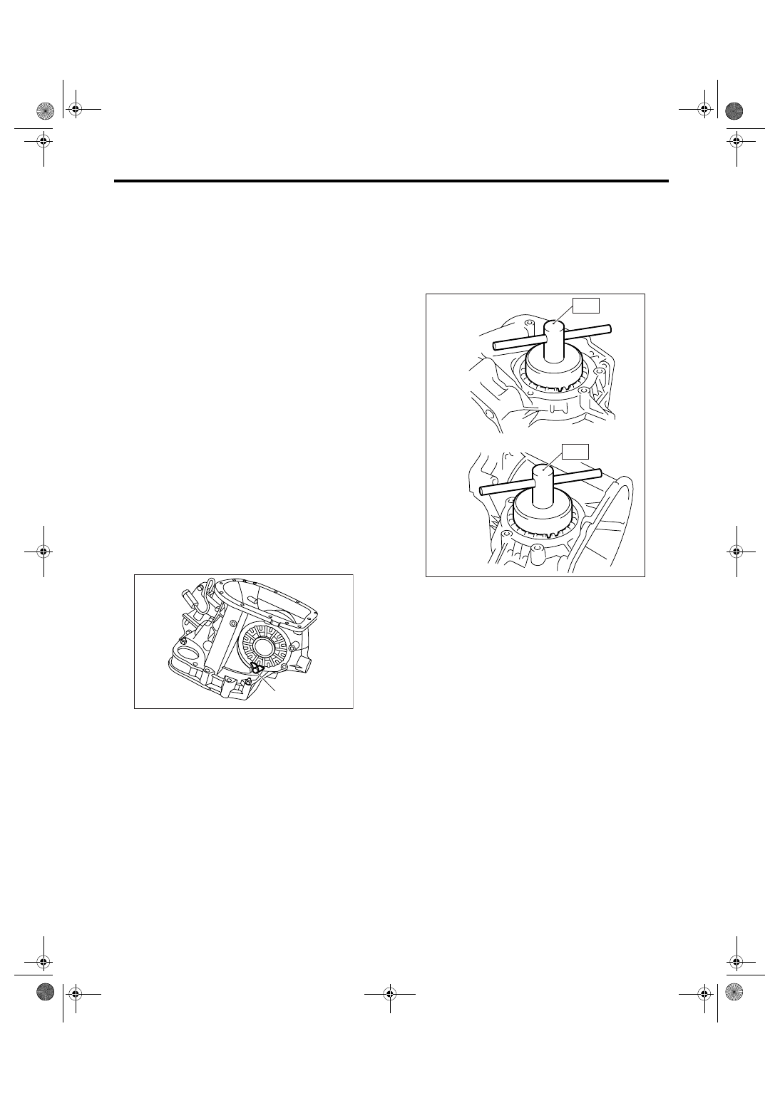
11) Remove the lock plates on both side.
12) Using the ST, remove the differential side re-
tainer on both side.
ST1
4939787000 WRENCH ASSY (RH SIDE)
ST2
18630AA000 WRENCH ASSY (LH SIDE)
NOTE:
Be careful not to damage the part of clutch case
where the retainer is to be installed.
13) Remove the front differential.
(A) Lock plate
(A)
MT-01022
(A) LH side
(B) RH side
(A)
(B)
MT-00657
ST1
ST2
Нет комментариевНе стесняйтесь поделиться с нами вашим ценным мнением.
Текст