Subaru Legacy (2005 year). Service manual — part 689
6MT-103
MANUAL TRANSMISSION AND DIFFERENTIAL
Front Differential Assembly
B: INSTALLATION
1) Install the differential assembly into clutch hous-
ing.
2) Apply gear oil to the threaded portion of side re-
tainer.
3) Remove the O-ring from side retainer of both
side.
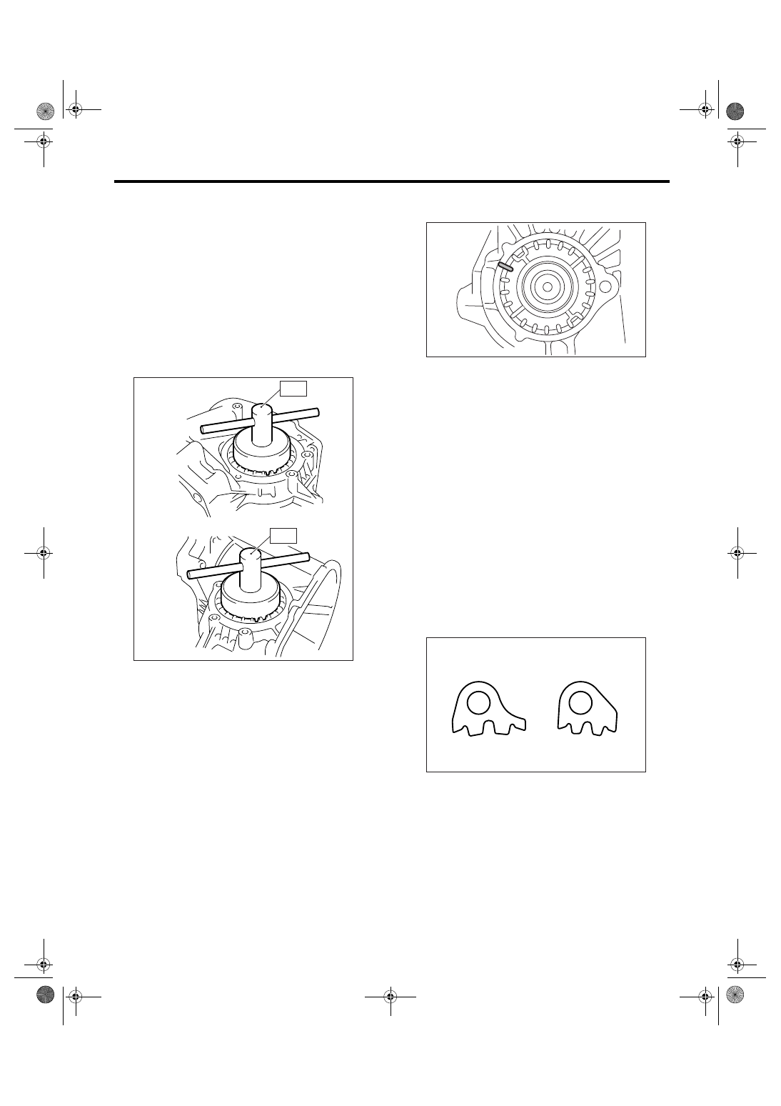
4) Using the ST, install the differential side retainer
to both side.
ST1
499787000
WRENCH ASSY (RH SIDE)
ST2
18630AA000 WRENCH ASSY (LH SIDE)
NOTE:
Be careful not to damage the oil seal.
5) Check and adjust the hypoid gear backlash.
<Ref. to 6MT-107, HYPOID GEAR BACKLASH,
INSPECTION, Front Differential Assembly.>
6) Check and adjust the tooth contact. <Ref. to
6MT-99, ADJUSTMENT, Drive Pinion Shaft As-
sembly.>
7) Put marks on the engagement position of the
right and left side retainer and clutch housing.
8) Remove the differential side retainer from both
side.
NOTE:
Record the rotating number of time till removal,
when removing the side retainer.
9) Install the O-ring to retainer on both side.
NOTE:
Always use a new O-ring.
10) Install the differential side retainer to both side.
NOTE:
Install the side retainer by screwing in the same ro-
tating number of time till removal, and then align
the marks.
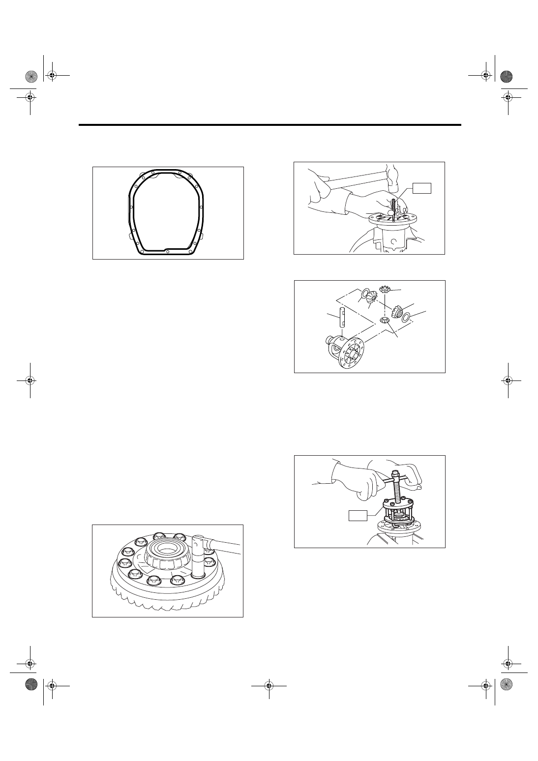
11) Install the lock plate.
Tightening torque:
25 N
⋅
m (2.5 kgf-m, 18.4 ft-lb)
NOTE:
Be careful not to confuse right and left lock plate.
12) Completely remove the remaining liquid gasket
from the clutch housing and adapter plate.
(A) LH side
(B) RH side
(A)
(B)
MT-00657
ST1
ST2
(A) LH
(B) RH
MT-00658
(A)
(B)
MT-00659
6MT-104
MANUAL TRANSMISSION AND DIFFERENTIAL
Front Differential Assembly
13) Apply liquid gasket to the clutch housing.
Liquid gasket:
THREE BOND 1215 (Part No. 004403007)
14) Install the drive pinion shaft assembly. <Ref. to
6MT-96, INSTALLATION, Drive Pinion Shaft As-
sembly.>
15) Install each gear assembly at a time. <Ref. to
6MT-70, INSTALLATION, Main Shaft Assembly.>
16) Install the transmission case. <Ref. to 6MT-65,
INSTALLATION, Transmission Case.>
17) Install the oil pump. <Ref. to 6MT-62, INSTAL-
LATION, Oil Pump.>
18) Install the center differential. <Ref. to 6MT-60,
INSTALLATION, Center Differential.>
19) Install the transfer driven gear. <Ref. to 6MT-
58, INSTALLATION, Transfer Driven Gear.>
20) Install the extension case. <Ref. to 6MT-47, IN-
STALLATION, Extension Case.>
21) Install the oil pipe, neutral position switch,
back-up light switch and harness. <Ref. to 6MT-42,
INSTALLATION, Oil Pipe.> <Ref. to 6MT-45, IN-
STALLATION, Neutral Position Switch.> <Ref. to
6MT-43, INSTALLATION, Back-up Light Switch.>
22) Install the manual transmission assembly into
vehicle. <Ref. to 6MT-36, INSTALLATION, Manual
Transmission Assembly.>
C: DISASSEMBLY
1. DIFFERENTIAL CASE
1) Secure the differential assembly on a vise, then
remove the hypoid driven gear.
2) Using the ST, drive out the straight pin from dif-
ferential assembly toward hypoid driven gear side.
ST
899904100
REMOVER
3) Pull out the pinion shaft, and remove the bevel
pinion gear and bevel gear and washer.
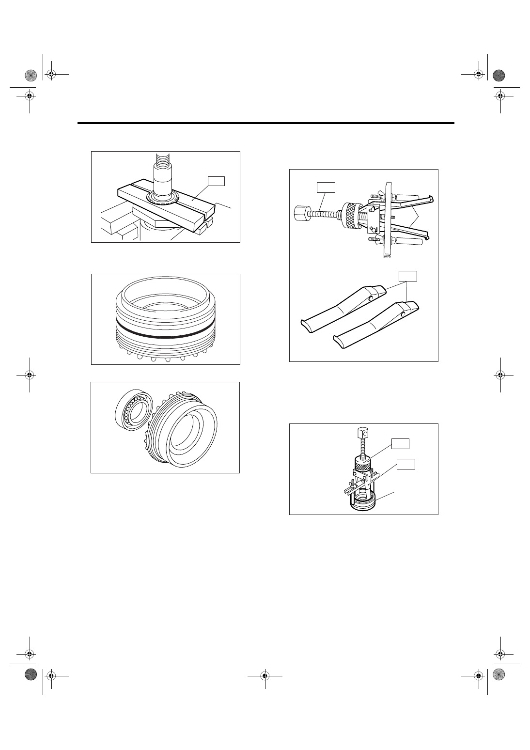
4) Using the ST, remove the hypoid driven gear
side bearing.
ST
399527700
PULLER SET
MT-00532
MT-00660
(A) Pinion shaft
(B) Bevel pinion gear
(C) Bevel gear
(D) Washer
ST
MT-00661
(A)
(B)
(B)
(C)
(C)
(D)
(D)
MT-00662
ST
MT-00663
6MT-105
MANUAL TRANSMISSION AND DIFFERENTIAL
Front Differential Assembly
5) Using the ST, remove the roller bearing.
ST
498077000
REMOVER
2. SIDE RETAINER
1) Remove the O-ring.
2) Remove the oil seal.
3) Remove the claw of ST1, and then install the
claw of ST2.
ST1
398527700
PULLER ASSY
ST2
18760AA000 CLAW
4) Using the ST, remove the bearing outer race
from side retainer.
ST1
398527700
PULLER ASSY
ST2
18760AA000 CLAW
ST
MT-00665
MT-00666
AT-00220
(A) Claw
(A) Side retainer
MT-00668
(A)
ST2
ST1
MT-00669
(A)
ST2
ST1
6MT-106
MANUAL TRANSMISSION AND DIFFERENTIAL
Front Differential Assembly
D: ASSEMBLY
1. DIFFERENTIAL CASE
1) Install the washer to bevel gear.
NOTE:
Face the chamfered side of washer toward gear.
2) Install the bevel gear and bevel pinion gear
washer to differential case, and then insert the pin-
ion shaft.
3) Check the bevel pinion gear backlash. <Ref. to
6MT-107, BEVEL PINION GEAR BACKLASH, IN-
SPECTION, Front Differential Assembly.>
4) Using the ST, align the pinion shaft and differen-
tial case with their holes, and drive straight pin into
holes.
ST
899904100
REMOVER
5) Caulk around the hole, be sure the straight pin is
not removed.
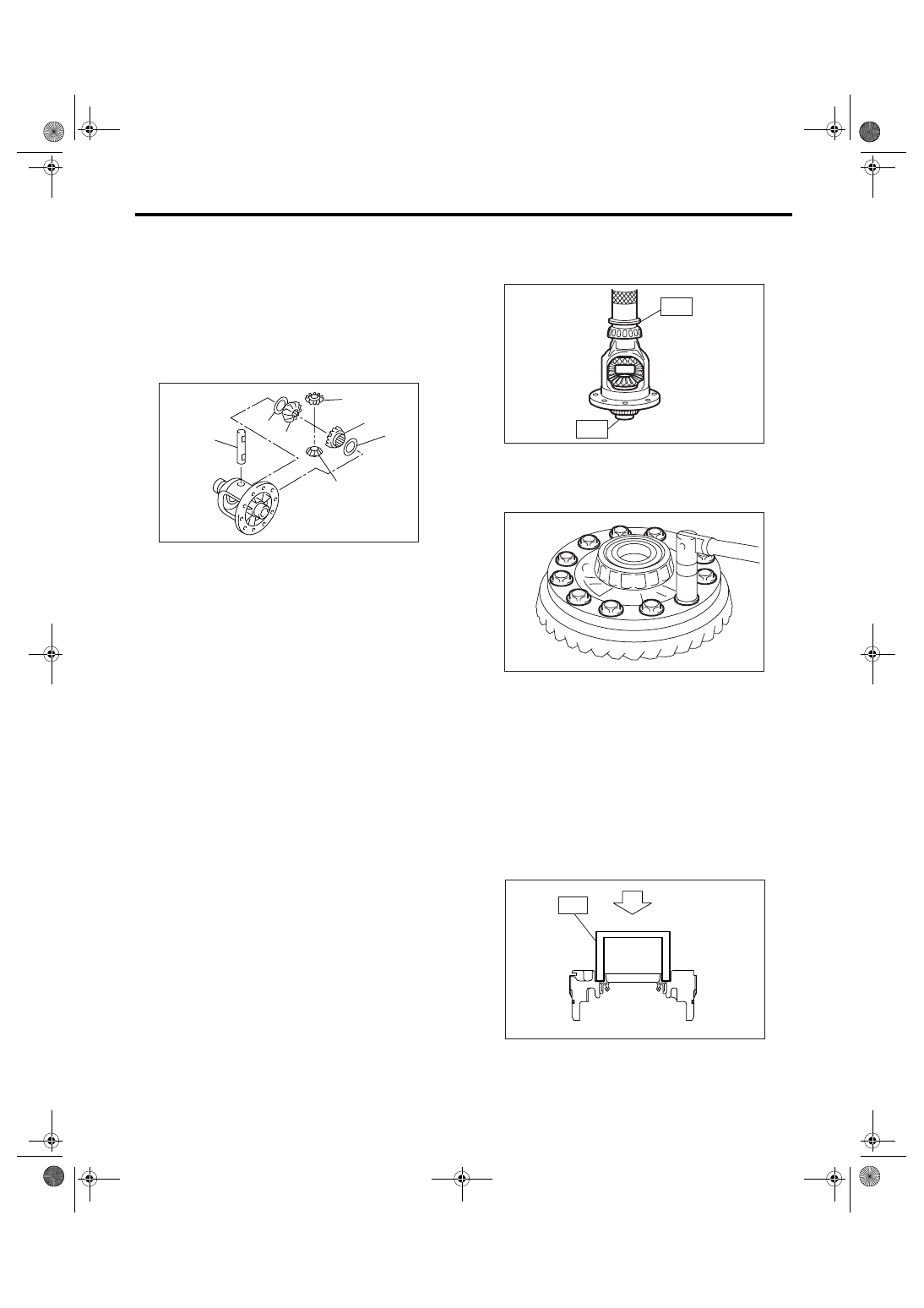
6) Using the ST, install the bearing inner races of
RH and LH side to differential case.
ST1
398437700
INSTALLER
ST2
398497701
SEAT
CAUTION:
Do not apply pressure in excess of 20 kN (2.0
ton, 2.2 US ton, 2.0 Imp ton).
NOTE:
Always replace the inner race and outer race as a
set.
7) Install the hypoid driven gear to differential case.
Tightening torque:
69 N
⋅
m (7.0 kgf-m, 50.9 ft-lb)
2. SIDE RETAINER
NOTE:
Install the oil seal and O-ring of side retainer after
the adjustment of backlash and tooth contact.
1) Install the bearing outer race to side retainer.
2) Install the oil seal using the ST.
ST
18675AA000
DIFFERENTIAL SIDE OIL
SEAL INSTALLER
NOTE:
• Use a new oil seal.
• Apply oil to the oil seal lips.
(A) Pinion shaft
(B) Bevel pinion gear
(C) Bevel gear
(D) Washer
(A)
(B)
(B)
(C)
(C)
(D)
(D)
MT-00662
ST1
ST2
MT-00670
MT-00660
AT-00226
ST
Нет комментариевНе стесняйтесь поделиться с нами вашим ценным мнением.
Текст