Subaru Legacy (2005 year). Service manual — part 854
PS-87
POWER ASSISTED SYSTEM (POWER STEERING)
Oil Pump
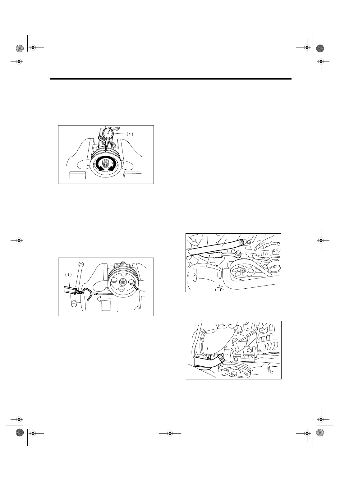
2) Ditch deflection of pulley
Service limit:
1.0 mm (0.039 in) or less
NOTE:
Read the value for one surface of V ditch, and then
the value for another off the dial.
3) Resistance to rotation of pulley
Service limit:
Maximum load: 9.22 N (0.94 kgf, 2.07 lbf) or
less
NOTE:
• A rather higher value may be indicated when pul-
ley starts turning.
• Measure the load during rotation to make a judg-
ment.
3. HYDRAULIC PRESSURE
NOTE:
• Be sure to complete all items aforementioned in
“INSPECTION”, prior to measuring hydraulic pres-
sure. Otherwise, pressure cannot be measured
correctly. <Ref. to PS-92, INSPECTION, General
Diagnostic Table.>
• Do not leave the valve of pressure gauge closed
or hold the steering wheel at stop end for 5 seconds
or more in any case, as the oil pump may be dam-
aged due to long keep of these conditions.
• Put cloth at a place where fluid drops before
pressure gauge is installed. Wipe off spilt fluid thor-
oughly after the measurement.
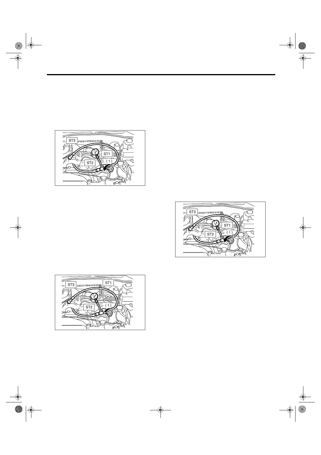
1) Regular pressure measurement
(1) Connect ST1, ST2 and ST3.
ST1
925711000
PRESSURE GAUGE
ST2
34099AC020 ADAPTER HOSE B
ST3
34099AC010 ADAPTER HOSE A
(2) Remove the air intake duct.
(3) Disconnect the pipe C from pump.
(4) Using the gasket (Part No. 34621AC021)
and bolt (Part No. 34620AC010), install the ST2
to pump instead of pressure hose.
• Non-turbo model
• Turbo model
(1) Dial gauge
(1) Spring balance
PS-00147
PS-00148
(1) Suction hose
(2) Pressure hose
(1) Suction hose
(2) Pressure hose
PS-00688
(1)
(2)
(2)
PS-00459
(1)
PS-88
POWER ASSISTED SYSTEM (POWER STEERING)
Oil Pump
(5) Install the ST3 to the end of pressure hose
which is removed from pump.
(6) Replenish the power steering fluid up to
specified level.
(7) Open the valve, and start the engine.
(8) Measure the regular pressure.
ST1
925711000
PRESSURE GAUGE
ST2
34099AC020 ADAPTER HOSE B
ST3
34099AC010 ADAPTER HOSE A
Service limit:
981 kPa (10 kgf/cm
2
, 142 psi) or less
(9) If it is not within the specification, replace the
troubled part caused by following symptoms.
(Pipe or hose clogged, leaks from fluid line, and
mixture of foreign matters in fluid line)
2) Measure the relief pressure.
(1) Using the ST, measure the relief pressure.
(2) Close the valve.
(3) Measure the relief pressure.
ST1
925711000
PRESSURE GAUGE
ST2
34099AC020 ADAPTER HOSE B
ST3
34099AC010 ADAPTER HOSE A
Service limit:
Non-turbo model (Except for 3.0 R model):
6,767 — 7,453 kPa (69 — 76 kgf/cm
2
, 981 —
1,081 psi)
Turbo model:
7,350 — 8,036 kPa (75 — 82 kgf/cm
2
, 1,067
— 1,165 psi)
3.0 R model:
8,300 — 9,000 kPa (85 — 92 kgf/cm
2
, 1,204
— 1,305 psi)
(4) If it is not within the specification, replace the
oil pump.
3) Measure working pressure.
(1) Using the ST, measure the working pres-
sure.
(2) Open the valve.
(3) Measure the working pressure of control
valve by turning steering wheel from stop to
stop.
ST1
925711000
PRESSURE GAUGE
ST2
34099AC020 ADAPTER HOSE B
ST3
34099AC010 ADAPTER HOSE A
Service limit:
7,650 — 8,330 kPa (78 — 85 kgf/cm
2
, 1,110 —
1,208 psi)
(4) If it is not within the specification, measure
the steering effort. <Ref. to PS-95, MEASURE-
MENT OF STEERING EFFORT, INSPECTION,
General Diagnostic Table.> If it is not within the
specification, replace the control valve itself or
control valve and pinion as a single unit with new
ones.
(1) Valve
(1) Valve
PS-00152
PS-00153
(1) Valve
PS-00152
PS-89
POWER ASSISTED SYSTEM (POWER STEERING)
Reservoir Tank
10.Reservoir Tank
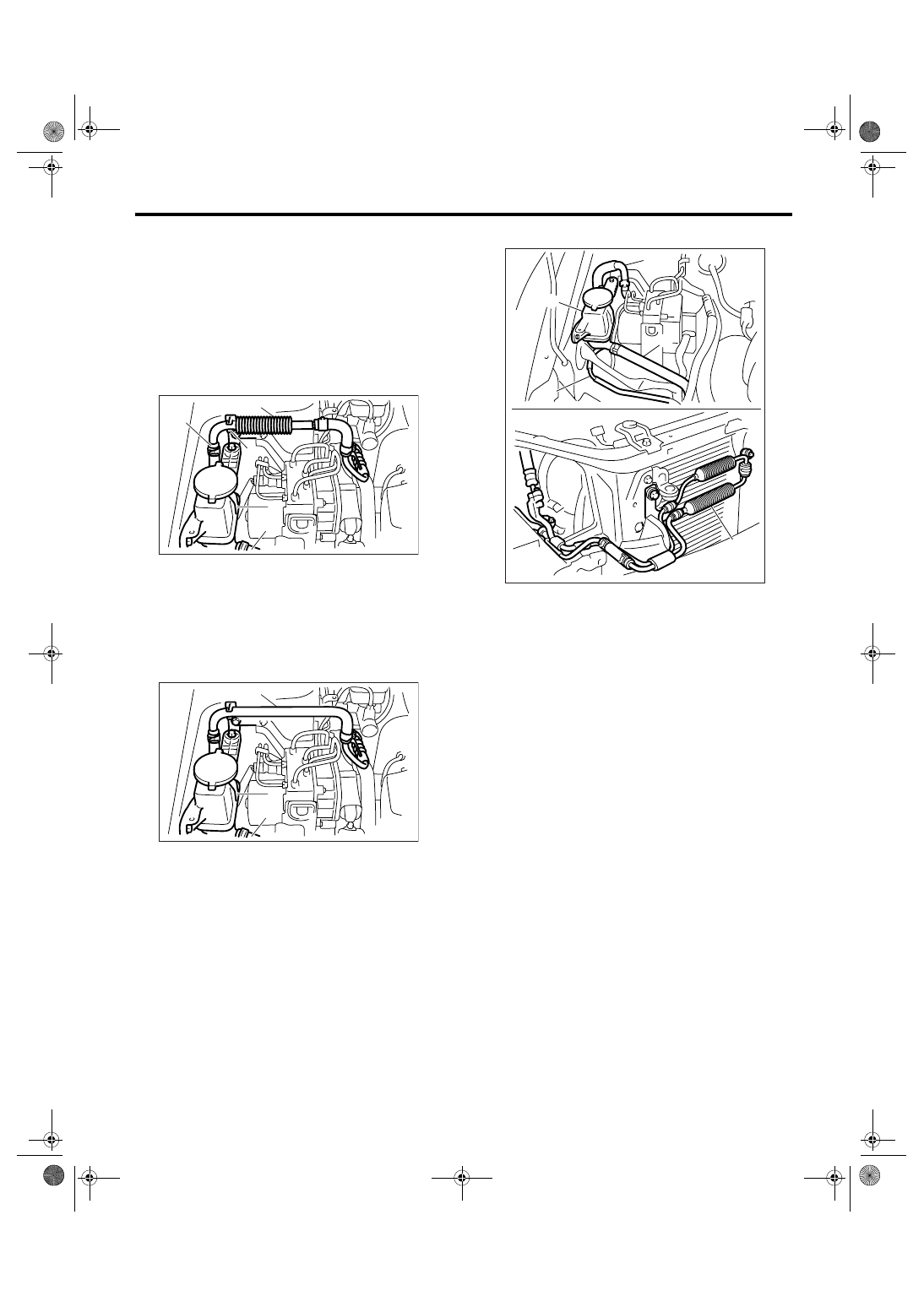
A: REMOVAL
1) Drain fluid from the reservoir tank.
2) Disconnect the hose from reservoir tank.
CAUTION:
To prevent foreign matter from entering the
hose and pipe, cover the open ends of them
with a clean cloth.
• H4 turbo model
• H4 non-turbo model
• H6 model
3) Remove the reservoir tank from body.
(1) Reservoir tank
(2) Suction hose
(3) Return hose
(4) Oil cooler
(5) Oil cooler bracket
(1) Reservoir tank
(2) Suction hose
(3) Return hose
PS-00482
(1)
(3)
(2)
(5)
(4)
PS-00697
(1)
(2)
(3)
(1) Reservoir tank
(2) Suction hose
(3) Return hose
(4) Oil cooler pipe
(5) Oil cooler
(3)
(4)
(5)
PS-00623
(2)
(1)
PS-90
POWER ASSISTED SYSTEM (POWER STEERING)
Reservoir Tank
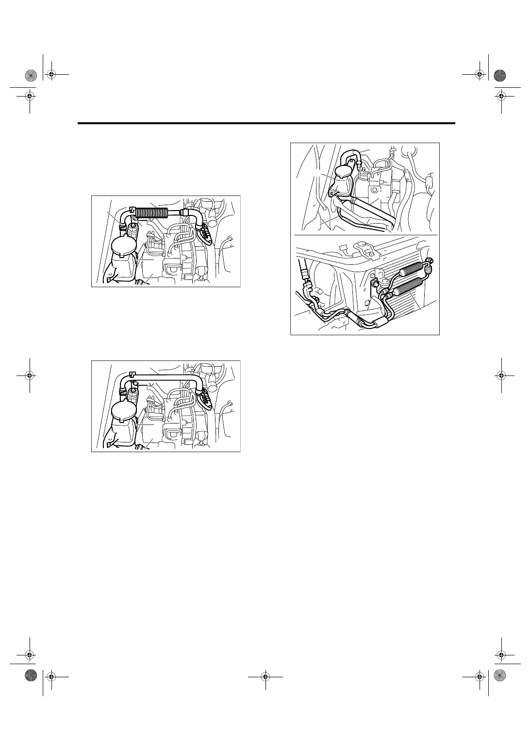
B: INSTALLATION
1) Install the reservoir tank to body.
Tightening torque:
13 N
⋅
m (1.3 kgf-m, 9.6 ft-lb)
2) Connect the hose to reservoir tank.
• H4 turbo model
• H4 non-turbo model
• H6 model
3) Feed the power steering fluid to specified level.
<Ref. to PS-91, Power Steering Fluid.>
C: INSPECTION
Check the reservoir tank for cracks, breakage or
damage. If a failure is found, replace the reservoir
tank.
(1) Reservoir tank
(2) Suction hose
(3) Return hose
(4) Oil cooler
(5) Oil cooler bracket
(1) Reservoir tank
(2) Suction hose
(3) Return hose
PS-00482
(1)
(3)
(2)
(5)
(4)
PS-00697
(1)
(2)
(3)
(1) Reservoir tank
(2) Suction hose
(3) Return hose
(4) Oil cooler pipe
(5) Oil cooler
(3)
(4)
(5)
PS-00623
(2)
(1)
Нет комментариевНе стесняйтесь поделиться с нами вашим ценным мнением.
Текст