Subaru Legacy (2005 year). Service manual — part 853
PS-83
POWER ASSISTED SYSTEM (POWER STEERING)
Oil Pump
B: INSTALLATION
1. H4 MODEL
1) Install the oil pump to bracket.
(1) Place the oil pump bracket in a vise. Tighten
the bushing using a 12.7 mm (1/2
″) type 14- and
21-mm box wrench until it is in contact with oil
pump mounting surface.
CAUTION:
When securing the oil pump bracket in a vise,
hold the oil pump bracket with the least possi-
ble force between two wood pieces.
(2) Tighten the bolt which holds the oil pump to
bracket.
Tightening torque:
15.7 N
⋅
m (1.6 kgf-m, 11.6 ft-lb)
Tightening torque:
37.3 N
⋅
m (3.8 kgf-m, 27.5 ft-lb)
2) Tighten the bolts which hold the power steering
pump bracket.
Tightening torque:
<Ref. to PS-9, OIL PUMP, COMPONENT, Gen-
eral Description.>
3) Interconnect the pressure hose and suction
hose.
Tightening torque:
Eye bolt
39 N
⋅
m (4.0 kgf-m, 28.9 ft-lb)
CAUTION:
If a hose is twisted at this step, take care the
hose may come into contact with some other
parts.
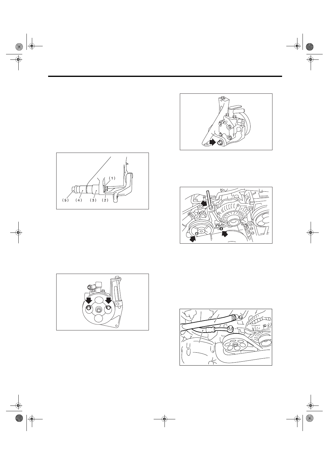
• Non-turbo model
(1) Bushing
(2) Nut
(3) 21 mm
(4) 14 mm
(5) Bolt
PS-00135
PS-00128
(1) Suction hose
(2) Pressure hose
PS-00137
PS-00188
PS-00688
(1)
(2)
PS-84
POWER ASSISTED SYSTEM (POWER STEERING)
Oil Pump
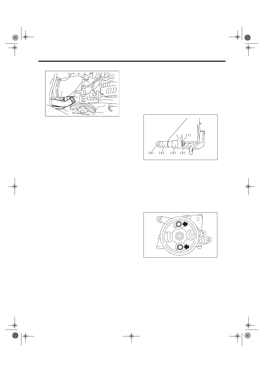
• Turbo model
4) Connect the connector to power steering pump
switch.
5) Install the V-belts to oil pump.
6) Check the tension of V-belt.
<Ref. to ME(H4SO 2.0)-38, INSPECTION, V-belt.>
7) Tighten the belt tension bolt.
Tightening torque:
25 N
⋅
m (2.5 kgf-m, 18.4 ft-lb)
8) Install the pulley belt cover.
9) Install the air intake duct.
<Ref. to IN(H4DOTC)-9, INSTALLATION, Air In-
take Duct.> <Ref. to IN(H4SO 2.0)-8, INSTALLA-
TION, Air Intake Duct.>
10) Connect the ground cable to battery.
11) Feed the specified power steering fluid. <Ref.
to PS-91, Power Steering Fluid.>
CAUTION:
Never start the engine before feeding the fluid
otherwise vane pump might be seized up.
2. H6 MODEL
1) Install the oil pump to bracket.
(1) Place the oil pump bracket in a vise. Tighten
the bushing using a 12.7 mm (1/2
″) type 14- and
21-mm box wrench until it is in contact with oil
pump mounting surface.
CAUTION:
When securing the oil pump bracket in a vise,
hold the oil pump bracket with the least possi-
ble force between two wood pieces.
(2) Tighten the bolt which installs oil pump to
bracket.
Tightening torque:
15.7 N
⋅
m (1.6 kgf-m, 11.6 ft-lb)
(1) Suction hose
(2) Pressure hose
(2)
PS-00459
(1)
(1) Bushing
(2) Nut
(3) 21 mm
(4) 14 mm
(5) Bolt
PS-00135
PS-00229
PS-85
POWER ASSISTED SYSTEM (POWER STEERING)
Oil Pump
Tightening torque:
37.3 N
⋅
m (3.8 kgf-m, 27.5 ft-lb)
2) Tighten the bolts which install power steering
pump bracket.
Tightening torque:
<Ref. to PS-9, OIL PUMP, COMPONENT, Gen-
eral Description.>
3) Connect the pressure hose and suction hose
each other.
Tightening torque:
Eye bolt
39 N
⋅
m (4.0 kgf-m, 28.9 ft-lb)
CAUTION:
If a hose is twisted at this step, take care the
hose may come into contact with some other
parts.
4) Connect the connector to power steering oil
pressure switch.
5) Install the tensioner adjuster.
6) Install the V-belts.
7) Install the cover of pully belt.
8) Connect the battery ground cable to battery.
9) Pour the specified power steering fluid. <Ref. to
PS-91, Power Steering Fluid.>
CAUTION:
Never start the engine before feeding the fluid;
otherwise vane pump might be seized up.
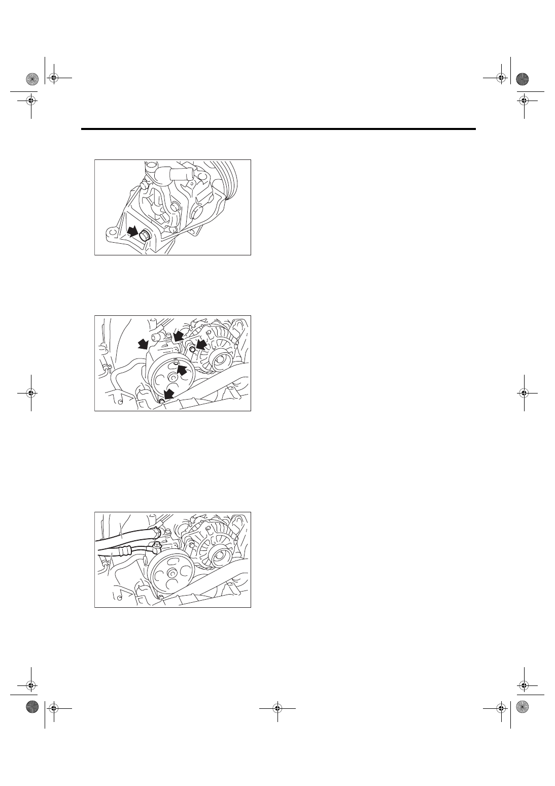
(1) Suction hose
(2) Pressure hose
PS-00702
PS-00701
PS-00700
(1)
(2)
PS-86
POWER ASSISTED SYSTEM (POWER STEERING)
Oil Pump
C: INSPECTION
1. BASIC INSPECTION
Perform the following inspection procedures and replace defective parts.
2. SERVICE LIMIT
Make a measurement as follows. If it exceeds the
service limit, replace with a new one.
CAUTION:
• When securing the oil pump on a vise, hold
the oil pump with the least possible force be-
tween two wood pieces.
• Do not set outside of flow control valve or
pulley on a vise; otherwise outside or pulley
might be deformed. Select properly sized wood
pieces.
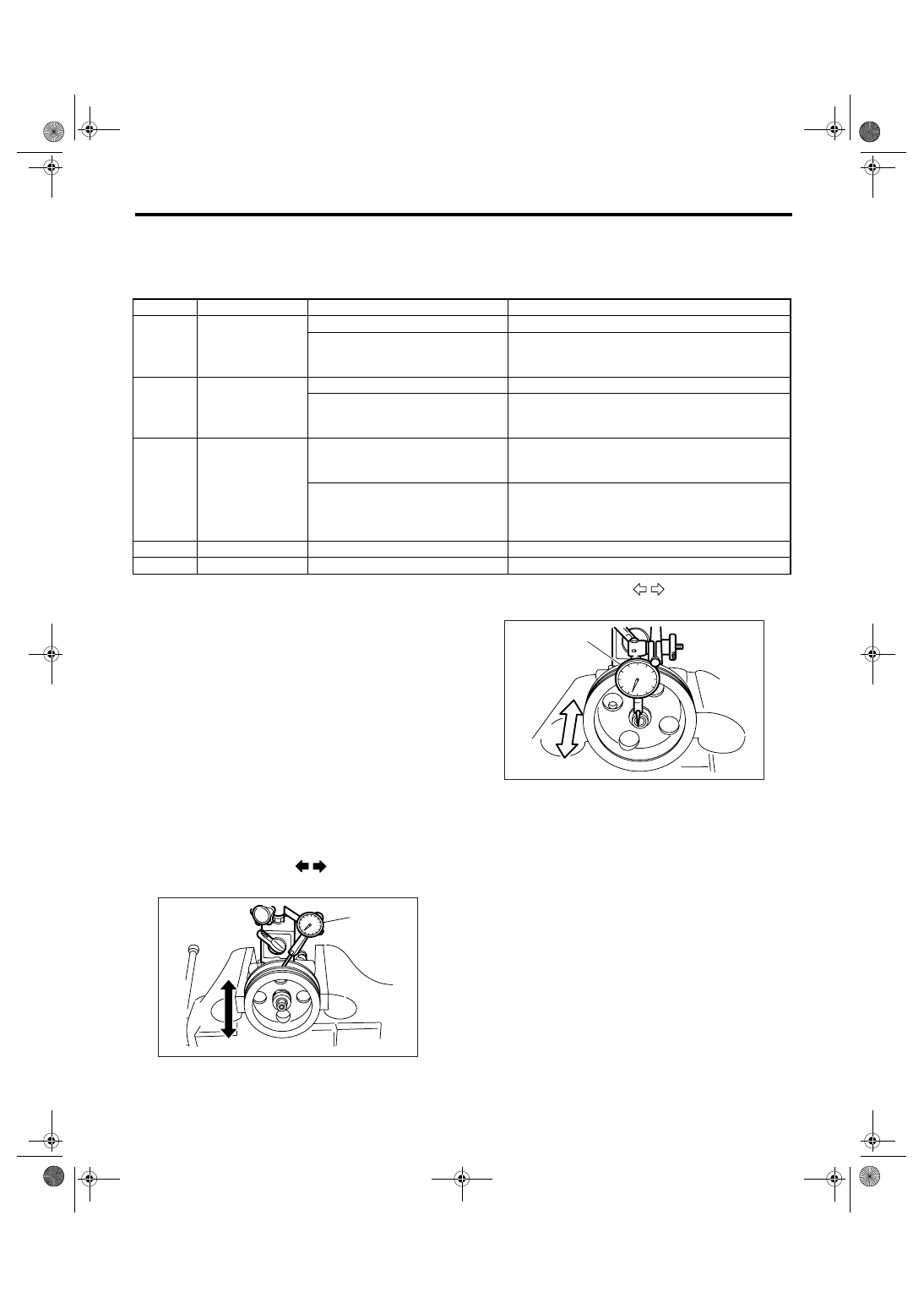
1) Play of the pulley shaft
Condition:
P: When applying the force of 9.8 N (1.0 kgf,
2.2 lbf)
Service limit:
Radial play (Direction
)
0.4 mm (0.016 in) or less
Axial play (Direction
)
0.9 mm (0.035 in) or less
No.
Parts
Inspection
Corrective action
1
Oil pump (Exterior)
(1) Crack, damage or oil leakage
Replace the oil pump with a new one.
(2) Play of pulley shaft
Measure the radial play and axial play.
If any of these exceeds the service limit, replace the
oil pump with a new one.
2
Pulley
(1) Damage
Replace with a new one.
(2) Bend
Measure the V ditch deflection.
If it exceeds the service limit, replace the pulley with a
new one.
3
Oil pump (Interior)
(1) Defect or burning of vane pump
Check the resistance to the rotation of pulley.
If it exceeds the service limit, replace the oil pump with
a new one.
(2) Bend in the shaft or damage to
bearing
Oil pump emits a noise that is markedly different in
tone and loudness from a sound of a new oil pump
when turning its pulley which is put around with a
string, replace the oil pump with a new one.
4
O-ring
Crack or deterioration
Replace with a new one.
5
Bracket
Crack
Replace with a new one.
(1) Dial gauge
PS-00145
P
(1)
(1) Dial gauge
PS-00146
P
(1)
Нет комментариевНе стесняйтесь поделиться с нами вашим ценным мнением.
Текст