Subaru Legacy (2005 year). Service manual — part 852
PS-79
POWER ASSISTED SYSTEM (POWER STEERING)
Pipe Assembly [RHD Model]
C: INSPECTION
Check all disassembled parts for wear, damage or other abnormalities. Repair or replace the defective parts
as necessary.
CAUTION:
Although surface layer materials of rubber hoses have excellent weathering resistance, heat resis-
tance and resistance for low temperature brittleness, they are likely to be damaged chemically by
brake fluid, battery electrolyte, engine oil and automatic transmission fluid and their service lives are
to be very shortened. Wipe out immediately when the hoses are adhered with the fluids.
Since resistances for heat or low temperature brittleness are gradually declining according to time
accumulation of hot or cold conditions for the hoses and their service lives are shortening accord-
ingly, it is necessary to perform careful inspection frequently when the vehicle is used in hot weather
areas, cold weather areas and a driving condition in which many steering operations are required in
short time.
Particularly continuous work of relief valve over 5 seconds causes to reduce service lives of the hos-
es, the oil pump, the fluid, etc. due to over heat.
Parts
Maintenance Parts
Corrective action
Pipe
• O-ring fitting surface for damage
• Nut for damage
• Pipe for damage
Replace with a new one.
Clamp
• Clamps for weak clamping force
Replace with a new one.
Hose
• Flare surface for damage
• Flare nut for damage
• Outer surface for cracks
• Outer surface for wear
• Clip for damage
• End coupling or adapter for deformation
Replace with a new one.
Trouble
Possible cause
Corrective action
Pressure hose burst
Excessive holding time of relief status
Instruct customers.
Malfunction of relief valve
Replace the oil pump.
Poor cold characteristic of fluid
Replace fluid.
Forced out return hose
Poor connection
Repair.
Poor holding of clip
Retighten.
Poor cold characteristic of fluid
Replace fluid.
Fluid bleeding out of hose
slightly
Wrong layout, tensioned
Replace the hose.
Excessive play of engine due to deterioration of
engine mounting rubber
Replace the parts if defective.
Improper stop position of pitching stopper
Replace the parts if defective.
Crack on hose
Excessive holding time of relief status
Replace.
Instruct customers.
Excessive tightening torque for return hose clip
Replace.
Power steering fluid, engine oil, electrolyte adhere
on the hose surface
Replace.
Pay attention on service work.
Too many times use in extremely cold weather
Replace.
Instruct customers.
PS-80
POWER ASSISTED SYSTEM (POWER STEERING)
Pipe Assembly [RHD Model]
NOTE:
It is likely that although one judges fluid leakage, there is actually no leakage. This is because the fluid spilt
during the last maintenance was not completely wiped off. Be sure to wipe off spilt fluid thoroughly after main-
tenance.
(A)
H6 model
(B)
H4 turbo model
(C)
H4 non-turbo model
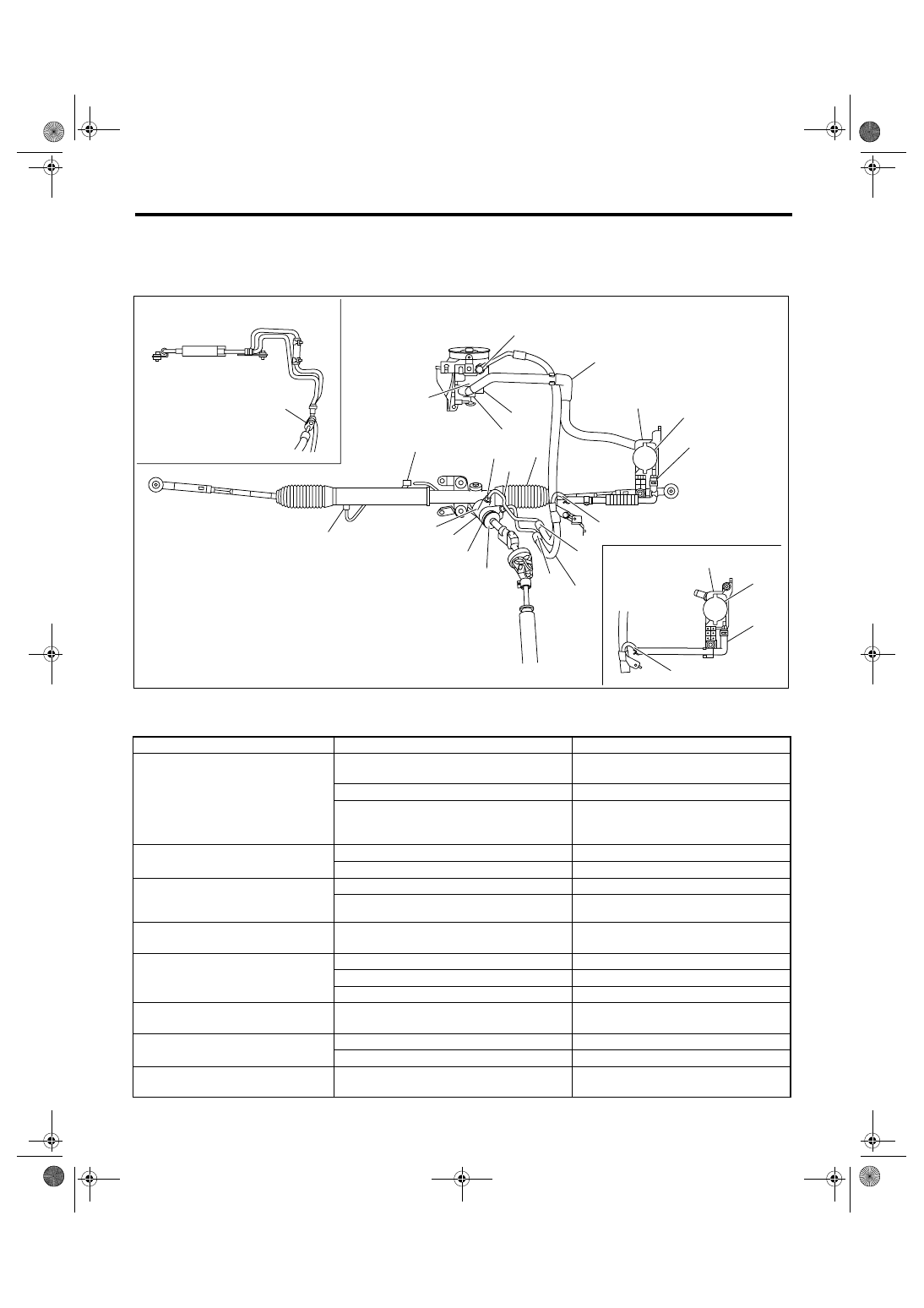
Fluid leaking area
Possible cause
Corrective action
Leakage from connecting portions of
pipes and hoses, numbered with (1)
through (10) in the figure
Insufficient tightening of flare nut, adhesion of
dirt, damage to flare or flare nut or eye bolt
Loosen and retighten. Replace if ineffec-
tive.
Poor insertion of hose or clamping
Retighten or replace the clamp.
Damaged O-ring or gasket
Replace O-ring or gasket pipe or hose
with new one, if ineffective, replace the
gearbox also.
Leakage from hose (11), (12) and
(13) in the figure
Crack or damage in hose
Replace with a new one.
Crack or damage in hose hardware
Replace with a new one.
Leakage from surrounding of cast iron
portion of oil pump (14) and (15) in
the figure
Damaged O-ring
Replace the oil pump.
Damaged gasket
Replace the oil pump.
Leakage from oil tank (16) and (17) in
the figure
Crack in oil tank
Replace the oil tank.
Leakage from filler neck (18)
Damaged cap packing
Replace the cap.
Crack in root of filler neck
Replace the oil tank.
High fluid level
Adjust the fluid level.
Leakage from surrounding of power
cylinder of gearbox (19) in the figure
Damaged oil seal
Replace the oil seal.
Leakage from control valve of gear-
box (20) and (21) in the figure
Damaged packing or oil seal
Replace the problem parts.
Damage in control valve
Replace the control valve.
(22) Leakage from the joints between
cooler pipe and hose.
Insufficient tightening of connecting portion.
Loosen and retighten.
PS-00698
(5)
(21)
(19)
(9)
(14)
(15)
(10)
(11)
(16)
(18)
(17)
(12)
(13)
(7)
(8)
(20)
(4)
(3)
(6)
(1)
(2)
(22)
(A)
(B)
(C)
(16)
(18)
(17)
(12)
PS-81
POWER ASSISTED SYSTEM (POWER STEERING)
Oil Pump
9. Oil Pump
A: REMOVAL
1. H4 MODEL
1) Disconnect the ground cable from battery.
2) Remove the air intake duct. <Ref. to
IN(H4DOTC)-9, REMOVAL, Air Intake Duct.>
<Ref. to IN(H4SO 2.0)-8, REMOVAL, Air Intake
Duct.>
3) Remove the pulley belt cover.
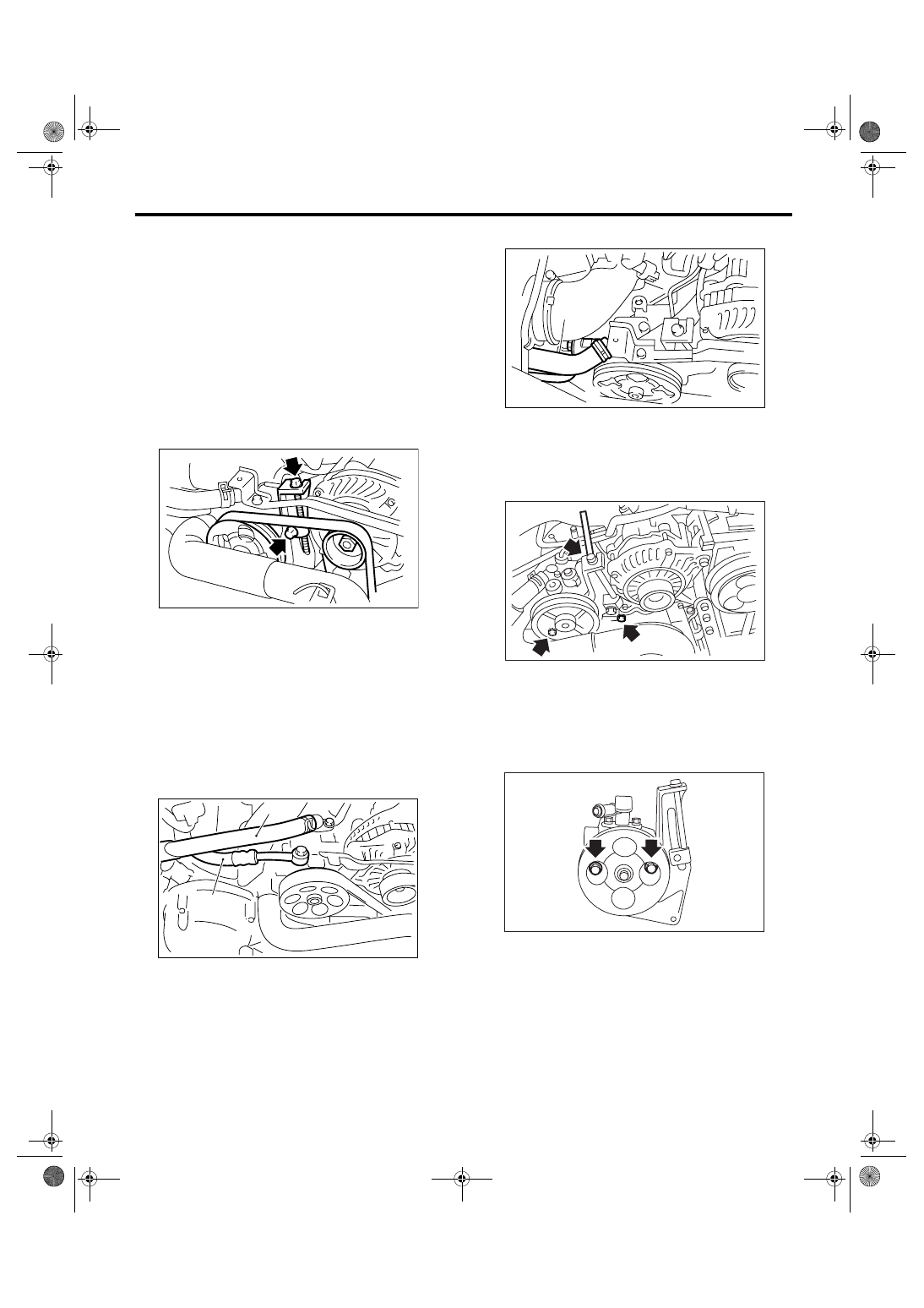
4) Loosen the belt tension securing bolt and gener-
ator securing bolt, and then remove the power
steering pump V-belt.
5) Disconnect the connector from power steering
pump switch.
6) Disconnect the pressure hose and suction hose
from oil pump.
CAUTION:
• Do not allow fluid to come into contact with
pulley belt.
• To prevent foreign matter from entering the
hose and pipe, cover the open ends with a
clean cloth.
• Non-turbo model
• Turbo model
7) Remove the bolts which hold the power steering
pump bracket.
8) Place the oil pump bracket in a vise, and remove
the two bolts from the front side of oil pump.
CAUTION:
When securing the oil pump bracket in a vise,
hold the oil pump bracket with the least possi-
ble force between two wood pieces.
9) Remove the bolt from the rear side of oil pump.
(1) Suction hose
(2) Pressure hose
PS-00461
PS-00688
(1)
(2)
(1) Suction hose
(2) Pressure hose
(2)
PS-00459
(1)
PS-00188
PS-00128
PS-82
POWER ASSISTED SYSTEM (POWER STEERING)
Oil Pump
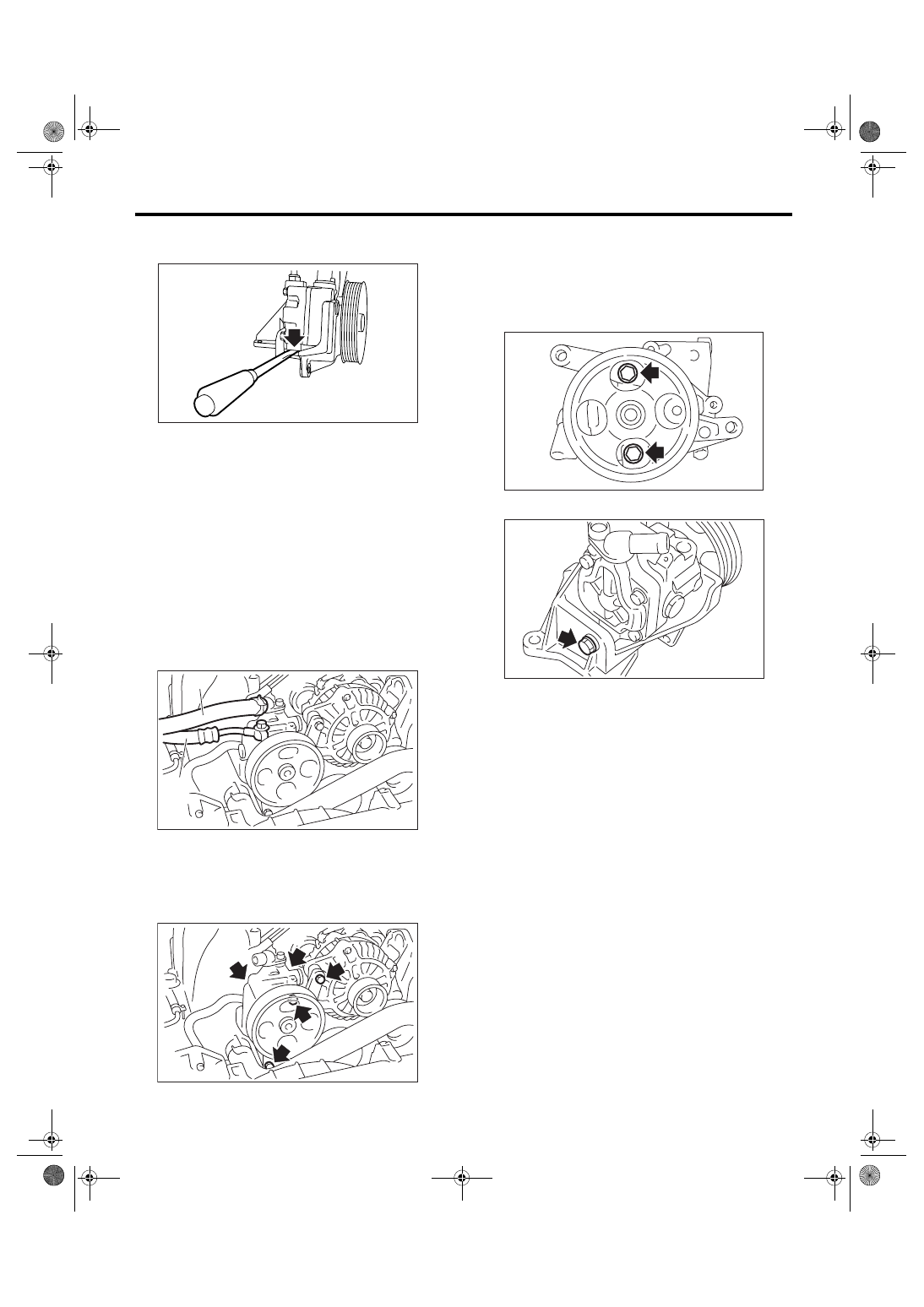
10) Disassemble the oil pump and bracket by in-
serting a flat tip screwdriver as shown in the figure.
2. H6 MODEL
1) Disconnect the ground cable from battery.
2) Remove the cover of pully belt.
3) Remove the V-belt.
4) Remove the power steering pressure switch
connector.
5) Remove the tensioner adjuster.
6) Disconnect the pressure hose and suction hose
from the oil pump.
CAUTION:
• Do not allow fluid to flow from the hose end
and to contact pully belt.
• To prevent entering foreign matter into hose,
cover the hose opening with clean cloth.
7) Remove the bolts which install power steering
pump bracket.
8) Place the oil pump bracket in a vise, and remove
the two bolts from the front side of oil pump.
CAUTION:
When securing the oil pump bracket in a vise,
hold the oil pump bracket with the least possi-
ble force between two wood pieces.
9) Remove the bolt from back side of oil pump.
10) Remove the oil pump from bracket.
(1) Suction hose
(2) Pressure hose
PS-00129
PS-00700
(1)
(2)
PS-00701
PS-00229
PS-00702
Нет комментариевНе стесняйтесь поделиться с нами вашим ценным мнением.
Текст