Subaru Legacy (2005 year). Service manual — part 471

EN(H6DO)(diag)-197
ENGINE (DIAGNOSTICS)
Diagnostic Procedure with Diagnostic Trouble Code (DTC)
Step
Check
Yes
No
1
CHECK ANY OTHER DTC ON DISPLAY.
Is any other DTC displayed?
Inspect the rele-
vant DTC using
“List of Diagnostic
Trouble Code
(DTC)”. <Ref. to
EN(H6DO)(diag)-
66, List of Diag-
nostic Trouble
Code (DTC).>
2
CHECK POWER SUPPLY OF CAMSHAFT
POSITION SENSOR.
1) Turn the ignition switch to OFF.
2) Disconnect the connector from camshaft
position sensor.
3) Measure the voltage between camshaft
position sensor connector and engine ground.
Connector & terminal
(E73) No. 1 (+) — Engine ground (
−
):
Is the voltage more than 10 V? Repair the battery
short circuit
between main
relay connector
and camshaft
position sensor
connector.
3
CHECK POWER SUPPLY OF CAMSHAFT
POSITION SENSOR.
1) Turn the ignition switch to ON.
2) Measure the voltage between camshaft
position sensor connector and engine ground.
Connector & terminal
(E73) No. 1 (+) — Engine ground (
−
):
Is the voltage more than 10 V? Go to step 4.
Repair the open or
battery short cir-
cuit between main
relay connector
and camshaft
position sensor
connector.
4
CHECK HARNESS BETWEEN CAMSHAFT
POSITION SENSOR CONNECTOR AND
ECM.
1) Turn the ignition switch to OFF.
2) Disconnect the connector from ECM.
3) Measure the resistance between camshaft
position sensor connector and ECM.
Connector & terminal
(E73) No. 2 — (B135) No. 9:
(E73) No. 3 — (B136) No. 35:
Is the resistance less than 1
Ω?
Repair the open
circuit between
camshaft position
sensor and ECM.
5
CHECK HARNESS BETWEEN CAMSHAFT
POSITION SENSOR CONNECTOR AND
ECM.
Measure the resistance between camshaft
position sensor connector and engine ground.
Connector & terminal
(E73) No. 2 — Engine ground:
Is the resistance more than 1
M
Ω?
Repair the ground
short circuit
between camshaft
position sensor
and ECM.
6
CHECK CONDITION OF CAMSHAFT POSI-
TION SENSOR.
Is the camshaft position sensor
installation bolt tightened
securely?
Tighten the cam-
shaft position sen-
sor installation bolt
securely.
7
CHECK CAMSHAFT POSITION SENSOR.
Check waveform of camshaft position sensor.
<Ref. to EN(H6DO)(diag)-17, Engine Control
Module (ECM) I/O Signal.>
Is there any abnormality in
waveform?
Replace the cam-
shaft position sen-
sor. <Ref. to
FU(H6DO)-19,
Crankshaft Posi-
tion Sensor.>
8
CHECK POOR CONTACT.
Check poor contact in ECM connector.
Is there poor contact in ECM
connector?
Repair the poor
contact in ECM
connector.
Replace the ECM.
<Ref. to
FU(H6DO)-34,
Engine Control
Module (ECM).>
EN(H6DO)(diag)-198
ENGINE (DIAGNOSTICS)
Diagnostic Procedure with Diagnostic Trouble Code (DTC)
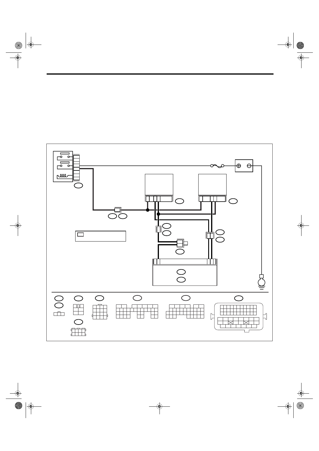
BL:DTC P0345 CAMSHAFT POSITION SENSOR “A” CIRCUIT (BANK 2)
DTC DETECTING CONDITION:
Immediately at fault recognition
TROUBLE SYMPTOM:
• Engine stalls.
• Failure of engine to start
CAUTION:
After repair or replacement of faulty parts, conduct Clear Memory Mode <Ref. to EN(H6DO)(diag)-41,
OPERATION, Clear Memory Mode.> and Inspection Mode <Ref. to EN(H6DO)(diag)-34, PROCEDURE,
Inspection Mode.>.
WIRING DIAGRAM:
EN-03501
B47
E
E2
B21
3
C35
SBF-7
E74
E1
B20
2
E73
B21
E2
1
19
3
B9
*
*
B83
2
1
ECM
B136
B135
B:
C:
48
1
3
4
1
2
5
6
B20
E74
B47
1 2 3
1 2 3 4
5 6 7 8
B83
B136
5
6
7 8
2
1
9
4
3
10
24
22 23
25
11 12 13 14 15
26 27
28
16
17 18 19 20 21
33 34
29
32
30
31
35
B135
5
6
7
8
2
1
9
4
3
10
24
22 23
25
11 12 13 14 15
26 27
28
16 17 18 19
20 21
29 30 31
32 33
34 35
E73
BATTERY
CAMSHAFT
POSITION
SENSOR RH
CAMSHAFT
POSITION
SENSOR LH
MAIN RELAY
B:
C:
2
B8
B21
1 2 3 4
12 13 14 15
5 6 7 8
16 17 18 19
9 10 11
20 21 22
23 24 25 26 27 28 29 30 31 32 33
35
34
37
36
39
38
41
40
43
42
44
45
47
46
49
48
51
50
53
52
54
6
4
: TERMINAL No.
RANDOM ARRANGEMENT
*
1 2 3 4
5 6 7 8
9 10 11 12
14
13
15 16

EN(H6DO)(diag)-199
ENGINE (DIAGNOSTICS)
Diagnostic Procedure with Diagnostic Trouble Code (DTC)
Step
Check
Yes
No
1
CHECK ANY OTHER DTC ON DISPLAY.
Is any other DTC displayed?
Inspect the rele-
vant DTC using
“List of Diagnostic
Trouble Code
(DTC)”. <Ref. to
EN(H6DO)(diag)-
66, List of Diag-
nostic Trouble
Code (DTC).>
2
CHECK POWER SUPPLY OF CAMSHAFT
POSITION SENSOR.
1) Turn the ignition switch to OFF.
2) Disconnect the connector from camshaft
position sensor.
3) Measure the voltage between camshaft
position sensor connector and engine ground.
Connector & terminal
(E74) No. 1 (+) — Engine ground (
−
):
Is the voltage more than 10 V? Repair the battery
short circuit
between main
relay connector
and camshaft
position sensor
connector.
3
CHECK POWER SUPPLY OF CAMSHAFT
POSITION SENSOR.
1) Turn the ignition switch to ON.
2) Measure the voltage between camshaft
position sensor connector and engine ground.
Connector & terminal
(E74) No. 1 (+) — Engine ground (
−
):
Is the voltage more than 10 V? Go to step 4.
Repair the open or
battery short cir-
cuit between main
relay connector
and camshaft
position sensor
connector.
4
CHECK HARNESS BETWEEN CAMSHAFT
POSITION SENSOR CONNECTOR AND
ECM.
1) Turn the ignition switch to OFF.
2) Disconnect the connector from ECM.
3) Measure the resistance between camshaft
position sensor connector and ECM.
Connector & terminal
(E74) No. 2 — (B135) No. 8:
(E74) No. 3 — (B136) No. 35:
Is the resistance less than 1
Ω?
Repair the open
circuit between
camshaft position
sensor and ECM.
5
CHECK HARNESS BETWEEN CAMSHAFT
POSITION SENSOR CONNECTOR AND
ECM.
Measure the resistance between camshaft
position sensor connector and engine ground.
Connector & terminal
(E74) No. 2 — Engine ground:
Is the resistance more than 1
M
Ω?
Repair the ground
short circuit
between camshaft
position sensor
and ECM.
6
CHECK CONDITION OF CAMSHAFT POSI-
TION SENSOR.
Is the camshaft position sensor
installation bolt tightened
securely?
Tighten the cam-
shaft position sen-
sor installation bolt
securely.
7
CHECK CAMSHAFT POSITION SENSOR.
Check waveform of camshaft position sensor.
<Ref. to EN(H6DO)(diag)-17, Engine Control
Module (ECM) I/O Signal.>
Is there any abnormality in
waveform?
Replace the cam-
shaft position sen-
sor. <Ref. to
FU(H6DO)-20,
Camshaft Position
Sensor.>
8
CHECK POOR CONTACT.
Check poor contact in ECM connector.
Is there poor contact in ECM
connector?
Repair the poor
contact in ECM
connector.
Replace the ECM.
<Ref. to
FU(H6DO)-34,
Engine Control
Module (ECM).>
EN(H6DO)(diag)-200
ENGINE (DIAGNOSTICS)
Diagnostic Procedure with Diagnostic Trouble Code (DTC)
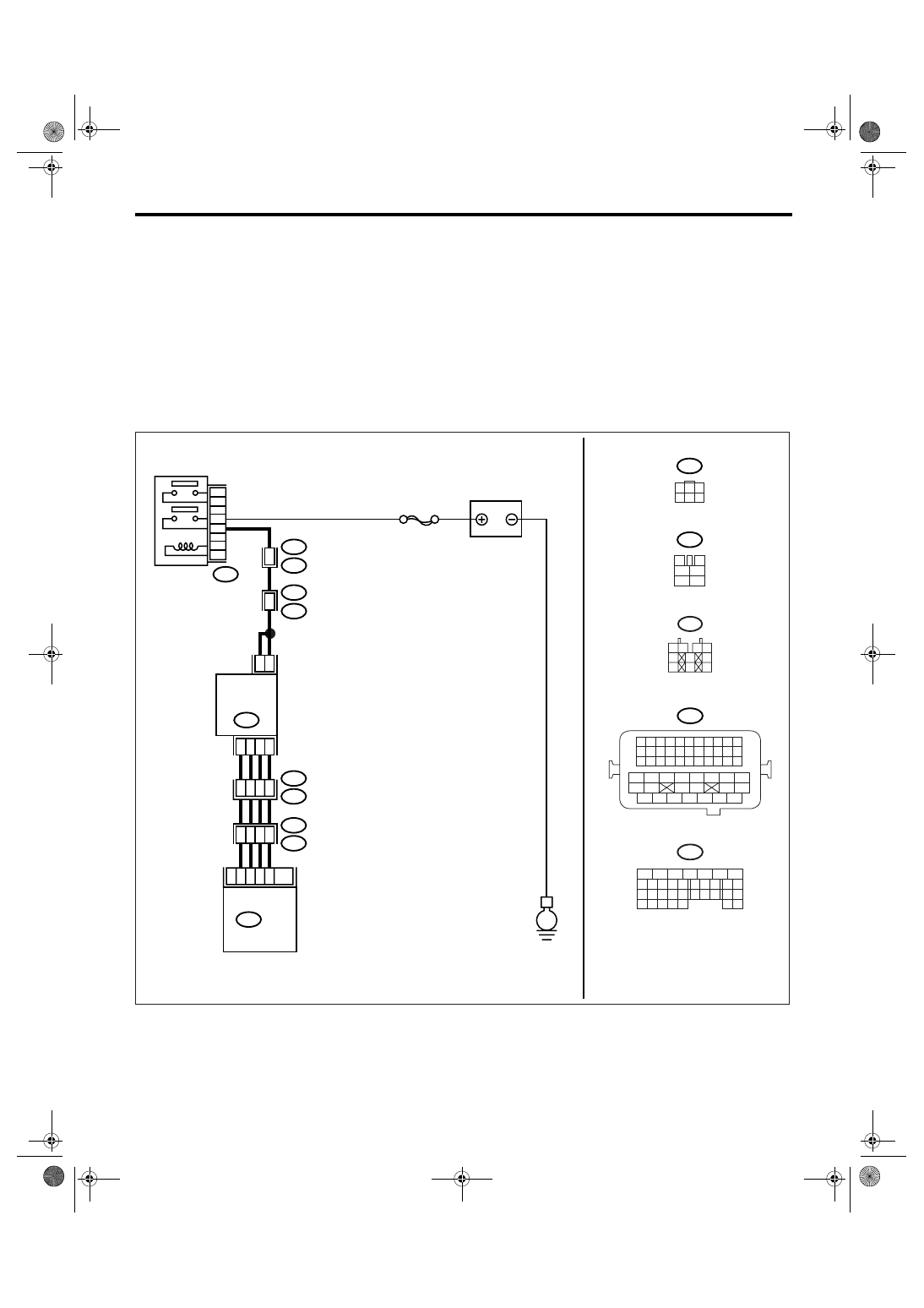
BM:DTC P0400 EXHAUST GAS RECIRCULATION FLOW
DTC DETECTING CONDITION:
Detects when malfunction occurs in 2 continuous driving cycles.
TROUBLE SYMPTOM:
• Movement performance problem when engine is low speed.
• Erroneous idling
• Movement performance problem
CAUTION:
After repair or replacement of faulty parts, conduct Clear Memory Mode <Ref. to EN(H6DO)(diag)-41,
OPERATION, Clear Memory Mode.> and Inspection Mode <Ref. to EN(H6DO)(diag)-34, PROCEDURE,
Inspection Mode.>.
WIRING DIAGRAM:
EN-03502
E
B47
E18
2
5
1
4
3
6
B21
E2
E76
E77
48
3
10
9
11
8
4
7
6
SBF-7
BATTERY
MAIN RELAY
EGR
VALVE
B134
ECM
B47
3
4
1
2
5
6
B21
1 2 3 4
12 13 14 15
5 6 7 8
16 17 18 19
9 10 11
20 21 22
23 24 25 26 27 28 29 30 31 32 33
35
34
37
36
39
38
41
40
43
42
44
45
47
46
49
48
51
50
53
52
54
5
6
7
8
2
1
9
4
3
10
24
22 23
25
11 12 13 14 15
26 27
28
16 17
18 19 20 21
33 34
29
32
30 31
B134
10
E76
E77
21
32
33
22
B21
E2
E18
1
3
4 5 6
2
1 2
3 4
5
6
7
8
9
10
E77
6
4
Нет комментариевНе стесняйтесь поделиться с нами вашим ценным мнением.
Текст