Subaru Legacy (2005 year). Service manual — part 472
EN(H6DO)(diag)-201
ENGINE (DIAGNOSTICS)
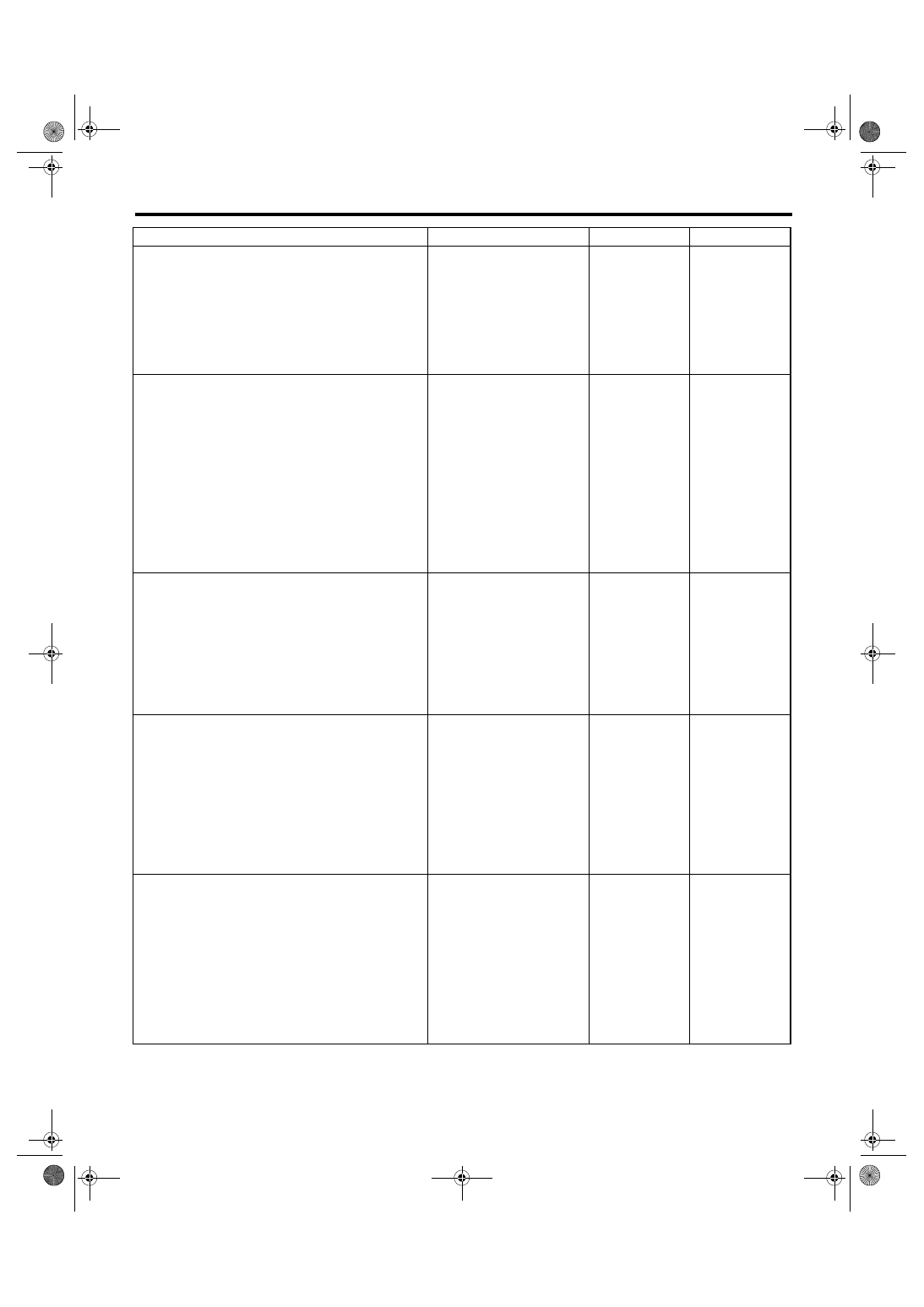
Diagnostic Procedure with Diagnostic Trouble Code (DTC)
Step
Check
Yes
No
1
CHECK ANY OTHER DTC ON DISPLAY.
Is any other DTC displayed?
Check DTC using
the List of Diag-
nostic Trouble
Code (DTC). <Ref.
to
EN(H6DO)(diag)-
66, List of Diag-
nostic Trouble
Code (DTC).>
2
CHECK CURRENT DATA.
1) Start the engine.
2) Read the data of intake manifold absolute
pressure signal using Subaru Select Monitor or
general scan tool.
NOTE:
• Subaru Select Monitor
For detailed operation procedure, refer to
“READ CURRENT DATA FOR ENGINE”. <Ref.
to EN(H6DO)(diag)-26, Subaru Select Moni-
tor.>
• General scan tool
For detailed operation procedure, refer to the
general scan tool operation manual.
Is the value 53.3 kPa (400
mmHg, 15.75 inHg) or more?
Make sure that the
EGR valve, mani-
fold absolute pres-
sure sensor and
throttle body are
installed securely.
3
CHECK POWER SUPPLY OF EGR SOLE-
NOID VALVE.
1) Detach the connector from EGR solenoid
valve.
2) Turn the ignition switch to ON.
3) Measure the voltage between EGR sole-
noid valve and engine ground.
Connector & terminal
(E18) No. 2 — Engine ground:
(E18) No. 5 — Engine ground:
Is the voltage more than 10 V? Go to step 4.
Repair the open
circuit of harness
between main
relay and EGR
solenoid valve
connector.
4
CHECK EGR SOLENOID VALVE.
Measure the resistance between EGR sole-
noid valve terminals.
NOTE:
Make sure there is no foreign material between
EGR solenoid valve and valve seat.
Terminal
No. 1 — No. 2:
No. 3 — No. 2:
No. 4 — No. 5:
No. 6 — No. 5:
Is the resistance 20 — 30
Ω?
Replace the EGR
solenoid valve.
<Ref. to
FU(H6DO)-25,
EGR Valve.>
5
OUTPUT SIGNAL FROM ECM
1) Turn the ignition switch to OFF.
2) Connect the connector to ECM and EGR
solenoid valve.
3) Turn the ignition switch to ON.
4) Measure the voltage between ECM and
chassis ground.
Connector & terminal
(B134) No. 8 (+) — Chassis ground (
−
):
(B134) No. 9 (+) — Chassis ground (
−
):
(B134) No. 10 (+) — Chassis ground (
−
):
(B134) No. 11 (+) — Chassis ground (
−
):
Is the voltage 0 — 10 V?
Repair the poor
contact in ECM
connector.
EN(H6DO)(diag)-202
ENGINE (DIAGNOSTICS)
Diagnostic Procedure with Diagnostic Trouble Code (DTC)
BN:DTC P0420 CATALYST SYSTEM EFFICIENCY BELOW THRESHOLD
(BANK1)
DTC DETECTING CONDITION:
Detects when malfunction occurs in 2 continuous driving cycles.
TROUBLE SYMPTOM:
• Engine stalls.
• Idle mixture is out of specifications.
CAUTION:
After repair or replacement of faulty parts, conduct Clear Memory Mode <Ref. to EN(H6DO)(diag)-41,
OPERATION, Clear Memory Mode.> and Inspection Mode <Ref. to EN(H6DO)(diag)-34, PROCEDURE,
Inspection Mode.>.
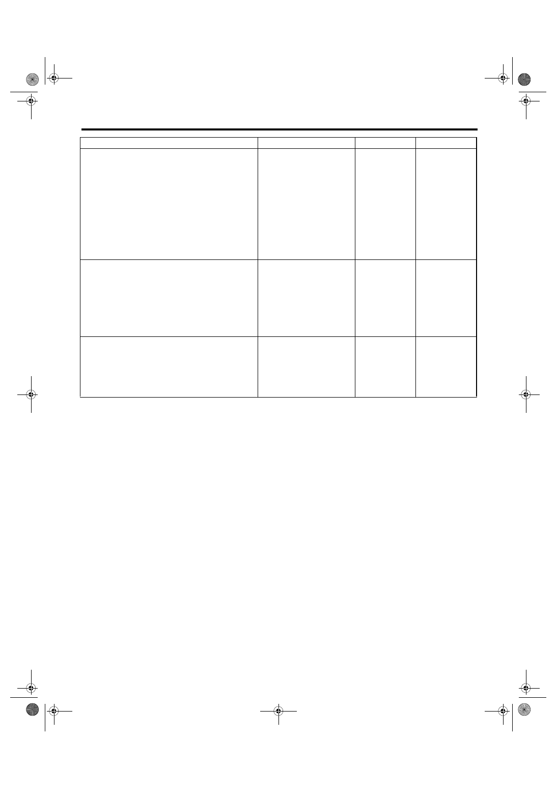
6
CHECK HARNESS BETWEEN EGR SOLE-
NOID VALVE AND ECM CONNECTOR.
1) Turn the ignition switch to OFF.
2) Detach the connector from EGR solenoid
valve and ECM.
3) Measure the resistance of harness
between EGR solenoid valve and ECM con-
nector.
Connector & terminal
(B134) No. 8 — (E18) No. 6:
(B134) No. 10 — (E18) No. 1:
(B134) No. 9 — (E18) No. 4:
(B134) No. 11 — (E18) No. 3:
Is the resistance less than 1
Ω?
Repair the open
circuit of harness
between ECM and
EGR solenoid
valve connector.
7
CHECK HARNESS BETWEEN EGR SOLE-
NOID VALVE AND ECM CONNECTOR.
Measure the resistance of harness between
EGR solenoid valve and chassis ground.
Connector & terminal
(B134) No. 8 — Chassis ground:
(B134) No. 9 — Chassis ground:
(B134) No. 10 — Chassis ground:
(B134) No. 11 — Chassis ground:
Is the resistance more than 1
M
Ω?
Repair the short
circuit of harness
between main
relay and EGR
solenoid valve
connector.
8
CHECK POOR CONTACT.
Check poor contact in ECM and EGR solenoid
valve connector.
Is there poor contact in ECM or
EGR solenoid valve connec-
tor?
Repair the poor
contact in ECM
and EGR solenoid
valve connector.
Even if the mal-
function indicator
light illuminates,
the circuit has
returned to a nor-
mal condition at
this time.
Step
Check
Yes
No
EN(H6DO)(diag)-203
ENGINE (DIAGNOSTICS)
Diagnostic Procedure with Diagnostic Trouble Code (DTC)
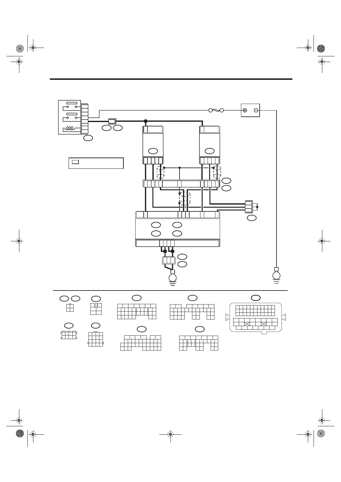
WIRING DIAGRAM:
BATTERY
SBF-5
B47
MAIN RELAY
A4
A5
A6
A7
2
52
54
B21
E2
ECM
B3
D31
D25
D24
B2
C35
4
3
1
REAR
OXYGEN
SENSOR LH
E25
2
4
3
1
REAR
OXYGEN
SENSOR RH
E61
E3
B22
14
13
15
E3
B22
10
11
12
9
B83
B47
3
4
5
6
1
2
EN-03495
B21
1 2 3 4
12 13 14 15
5 6 7 8
16 17 18 19
9 10 11
20 21 22
23 24 25 26 27 28 29 30 31 32 33
35
34
37
36
39
38
41
40
43
42
44
45
47
46
49
48
51
50
53
52
54
B135
5
6
7
8
2
1
9
4
3
10
24
22 23
25
11 12 13 14 15
26 27
28
16 17 18 19
20 21
29 30 31
32 33
34 35
B:
B134
5
6
7
8
2
1
9
4
3
10
24
22 23
25
11 12 13 14 15
26 27
28
16 17
18 19 20 21
33 34
29
32
30 31
A:
16
B134
A:
B135
B:
B136
C:
B137
D:
B22
1 2 3 4
5 6 7 8
9 10 11 12
13 14 15 16
B136
5
6
7 8
2
1
9
4
3
10
24
22 23
25
11 12 13 14 15
26 27
28
16
17 18 19 20 21
33 34
29
32
30
31
35
C:
B137
5
6
7
8
2
1
9
4
3
10
22 23
11 12 13 14 15
24 25
26
16 17
18 19 20 21
27
28 29
30 31
D:
1 2 3 4
5 6 7 8
B83
3 4
1 2
E25
E61
E
E
5
3
: TERMINAL No.
RANDOM ARRANGEMENT
*
*
*
*
EN(H6DO)(diag)-204
ENGINE (DIAGNOSTICS)
Diagnostic Procedure with Diagnostic Trouble Code (DTC)
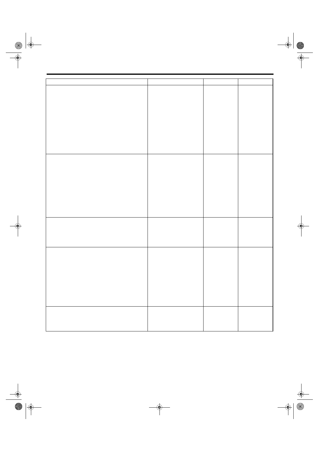
Step
Check
Yes
No
1
CHECK FOR ANY OTHER DTC ON DIS-
PLAY.
Is any other DTC displayed?
Inspect the rele-
vant DTC using
“List of Diagnostic
Trouble Code
(DTC)”. <Ref. to
EN(H6DO)(diag)-
66, List of Diag-
nostic Trouble
Code (DTC).>
NOTE:
In this case, it is
not necessary to
inspect DTC
P0420.
2
CHECK HARNESS BETWEEN ECM AND
REAR OXYGEN SENSOR CONNECTOR.
1) Turn the ignition switch to OFF.
2) Disconnect the connectors from ECM and
rear oxygen sensor.
3) Measure the resistance of harness
between ECM and rear oxygen sensor con-
nector.
Connector & terminal
(B137) No. 24 — (E61) No. 3:
(B136) No. 35 — (E61) No. 4:
(B137) No. 25 — (E25) No. 3:
(B136) No. 35 — (E25) No. 4:
Is the resistance less than 1
Ω?
Repair open circuit
in harness
between ECM and
rear oxygen sen-
sor connector.
3
CHECK HARNESS BETWEEN REAR OXY-
GEN SENSOR AND ECM CONNECTOR.
Measure the resistance between rear oxygen
sensor harness connector and chassis ground.
Connector & terminal
(B137) No. 31 — Chassis ground:
Is the resistance less than 1
Ω?
Repair the open
circuit between
ECM and rear oxy-
gen sensor con-
nector.
4
CHECK EXHAUST SYSTEM.
Check for gas leaks or air suction caused by
loose or dislocated nuts and bolts, and open
hole at exhaust pipes.
NOTE:
Check the following positions.
• Between cylinder head and front exhaust
pipe
• Between front exhaust pipe and front cata-
lytic converter
• Between front catalytic converter and rear
catalytic converter
Is there any fault in exhaust
system?
Repair or replace
the exhaust sys-
tem. <Ref. to
EX(H6DO)-2,
General Descrip-
tion.>
5
CHECK CATALYTIC CONVERTER.
Is there damage at rear face or
front face of front catalytic con-
verter?
Replace the cata-
lytic converter.
<Ref. to EC(H4SO
2.0)-3, Front Cata-
lytic Converter.>
Contact the SUB-
ARU dealer.
Нет комментариевНе стесняйтесь поделиться с нами вашим ценным мнением.
Текст