Subaru Legacy (2005 year). Service manual — part 470

EN(H6DO)(diag)-193
ENGINE (DIAGNOSTICS)
Diagnostic Procedure with Diagnostic Trouble Code (DTC)
Step
Check
Yes
No
1
CHECK HARNESS BETWEEN KNOCK SEN-
SOR AND ECM CONNECTOR.
Measure the resistance of harness between
ECM connector and chassis ground.
Connector & terminal
(B136) No. 24 — Chassis ground:
Is the resistance less than 400
k
Ω?
2
CHECK KNOCK SENSOR.
1) Disconnect the connector from knock sen-
sor.
2) Measure the resistance between knock
sensor connector terminal and engine ground.
Terminal
No. 2 — Engine ground:
Is the resistance less than 400
k
Ω?
Replace the knock
sensor. <Ref. to
FU(H6DO)-21,
Knock Sensor.>
Repair the ground
short circuit of har-
ness between
knock sensor con-
nector and ECM
connector.
NOTE:
The harness be-
tween both con-
nectors are
shielded. Repair
the short circuit of
harness covered
with shield.
3
CHECK INPUT SIGNAL OF ECM.
1) Connect the connectors to ECM and knock
sensor.
2) Turn the ignition switch to ON.
3) Measure the voltage between ECM and
chassis ground.
Connector & terminal
(B136) No. 24 (+) — Chassis ground (
−
):
Is the voltage more than 2 V?
Even if the mal-
function indicator
light illuminates,
the circuit has
returned to a nor-
mal condition at
this time. (How-
ever, the possibility
of poor contact still
remains.)
NOTE:
In this case, repair
the following:
• Poor contact in
knock sensor con-
nector
• Poor contact in
ECM connector
• Poor contact in
coupling connector
Repair the poor
contact in ECM
connector.
EN(H6DO)(diag)-194
ENGINE (DIAGNOSTICS)
Diagnostic Procedure with Diagnostic Trouble Code (DTC)
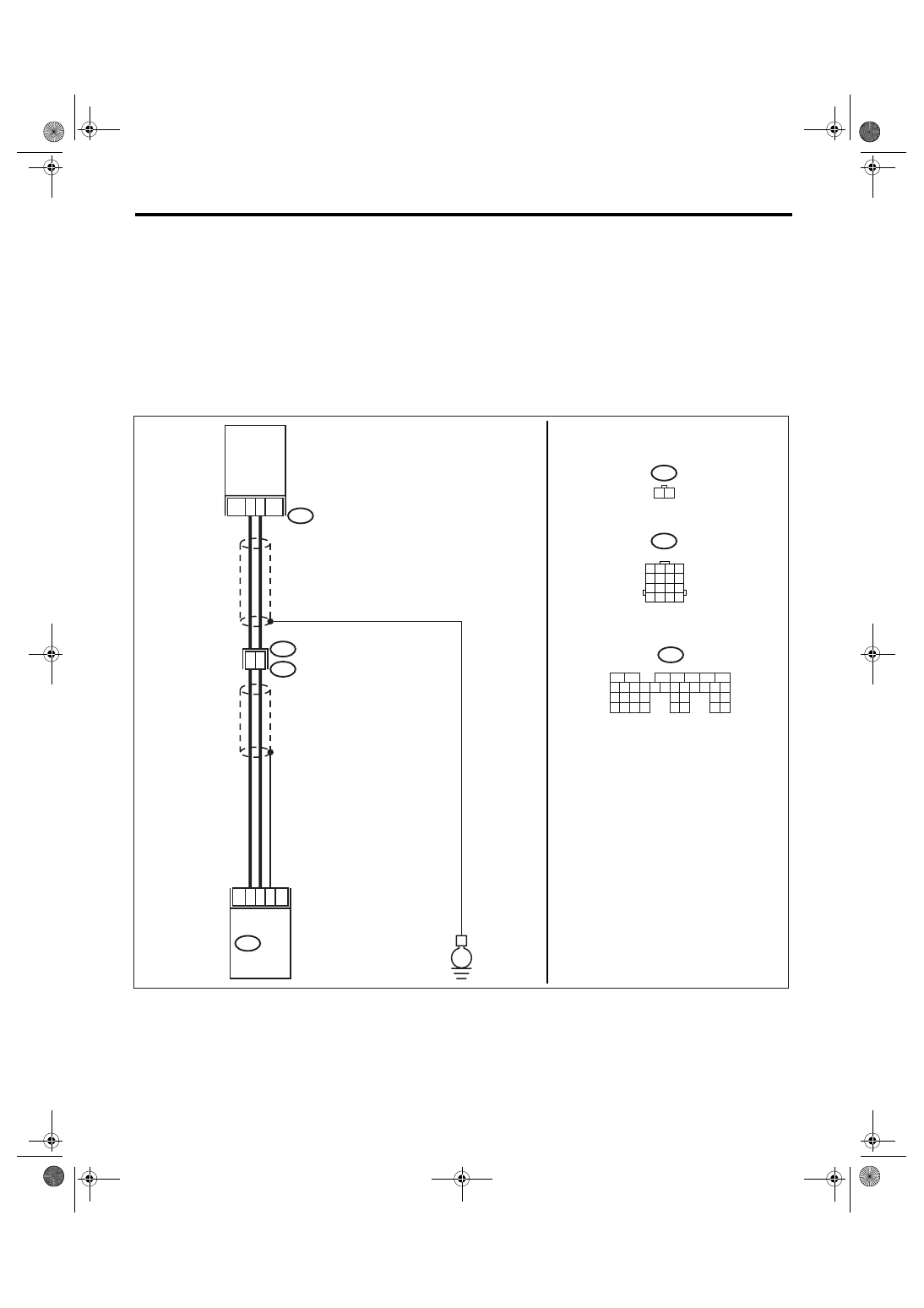
BJ:DTC P0335 CRANKSHAFT POSITION SENSOR “A” CIRCUIT
DTC DETECTING CONDITION:
Immediately at fault recognition
TROUBLE SYMPTOM:
• Engine stalls.
• Failure of engine to start
CAUTION:
After repair or replacement of faulty parts, conduct Clear Memory Mode <Ref. to EN(H6DO)(diag)-41,
OPERATION, Clear Memory Mode.> and Inspection Mode <Ref. to EN(H6DO)(diag)-34, PROCEDURE,
Inspection Mode.>.
WIRING DIAGRAM:
EN-02507
1
2
8
7
22
31
B20
E1
E10
E10
1 2
B135
ECM
CRANKSHAFT
POSITION
SENSOR
10
E
B20
B135
5
6
7
8
2
1
9
4
3
10
24
22 23
25
11 12 13 14 15
26 27
28
16 17 18 19
20 21
29 30 31
32 33
34 35
1 2 3 4
5 6 7 8
9 10 11 12
13 14 15 16
EN(H6DO)(diag)-195
ENGINE (DIAGNOSTICS)
Diagnostic Procedure with Diagnostic Trouble Code (DTC)
Step
Check
Yes
No
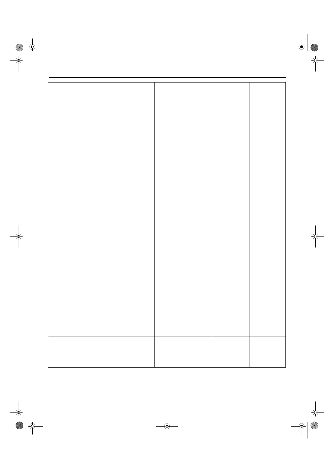
1
CHECK HARNESS BETWEEN CRANK-
SHAFT POSITION SENSOR AND ECM CON-
NECTOR.
1) Turn the ignition switch to OFF.
2) Disconnect the connector from crankshaft
position sensor.
3) Measure the resistance of harness
between crankshaft position sensor connector
and engine ground.
Connector & terminal
(E10) No. 1 — Engine ground:
Is the resistance more than
100 k
Ω?
Repair the har-
ness and connec-
tor.
NOTE:
In this case, repair
the following:
• Open circuit of
harness between
crankshaft posi-
tion sensor and
ECM connector
• Poor contact in
ECM connector
• Poor contact in
coupling connector
2
CHECK HARNESS BETWEEN CRANK-
SHAFT POSITION SENSOR AND ECM CON-
NECTOR.
Measure the resistance of harness between
crankshaft position sensor connector and
engine ground.
Connector & terminal
(E10) No. 1 — Engine ground:
Is the resistance less than 10
Ω?
Repair the ground
short circuit of har-
ness between
crankshaft posi-
tion sensor and
ECM connector.
NOTE:
The harness be-
tween both con-
nectors are
shielded. Repair
the ground short
circuit of harness
with shield.
3
CHECK HARNESS BETWEEN CRANK-
SHAFT POSITION SENSOR AND ECM CON-
NECTOR.
Measure the resistance of harness between
crankshaft position sensor connector and
engine ground.
Connector & terminal
(E10) No. 2 — Engine ground:
Is the resistance less than 5
Ω?
Repair the har-
ness and connec-
tor.
NOTE:
In this case, repair
the following:
• Open circuit of
harness between
crankshaft posi-
tion sensor and
ECM connector
• Poor contact in
ECM connector
• Poor contact in
coupling connector
4
CHECK CONDITION OF CRANKSHAFT PO-
SITION SENSOR.
Is the crankshaft position sen-
sor installation bolt tightened
securely?
Tighten the crank-
shaft position sen-
sor installation bolt
securely.
5
CHECK CRANKSHAFT POSITION SENSOR.
1) Remove the crankshaft position sensor.
2) Measure the resistance between connector
terminals of crankshaft position sensor.
Terminal
No. 1 — No. 2:
Is the resistance 1 — 4 k
Ω?
Repair the poor
contact in crank-
shaft position sen-
sor connector.
Replace the crank-
shaft position sen-
sor. <Ref. to
FU(H6DO)-19,
Crankshaft Posi-
tion Sensor.>
EN(H6DO)(diag)-196
ENGINE (DIAGNOSTICS)
Diagnostic Procedure with Diagnostic Trouble Code (DTC)
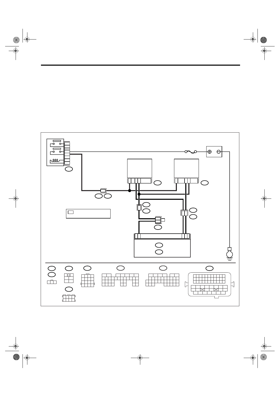
BK:DTC P0340 CAMSHAFT POSITION SENSOR “A” CIRCUIT (BANK 1 OR SIN-
GLE SENSOR)
DTC DETECTING CONDITION:
Immediately at fault recognition
TROUBLE SYMPTOM:
• Engine stalls.
• Failure of engine to start
CAUTION:
After repair or replacement of faulty parts, conduct Clear Memory Mode <Ref. to EN(H6DO)(diag)-41,
OPERATION, Clear Memory Mode.> and Inspection Mode <Ref. to EN(H6DO)(diag)-34, PROCEDURE,
Inspection Mode.>.
WIRING DIAGRAM:
EN-03501
B47
E
E2
B21
3
C35
SBF-7
E74
E1
B20
2
E73
B21
E2
1
19
3
B9
*
*
B83
2
1
ECM
B136
B135
B:
C:
48
1
3
4
1
2
5
6
B20
E74
B47
1 2 3
1 2 3 4
5 6 7 8
B83
B136
5
6
7 8
2
1
9
4
3
10
24
22 23
25
11 12 13 14 15
26 27
28
16
17 18 19 20 21
33 34
29
32
30
31
35
B135
5
6
7
8
2
1
9
4
3
10
24
22 23
25
11 12 13 14 15
26 27
28
16 17 18 19
20 21
29 30 31
32 33
34 35
E73
BATTERY
CAMSHAFT
POSITION
SENSOR RH
CAMSHAFT
POSITION
SENSOR LH
MAIN RELAY
B:
C:
2
B8
B21
1 2 3 4
12 13 14 15
5 6 7 8
16 17 18 19
9 10 11
20 21 22
23 24 25 26 27 28 29 30 31 32 33
35
34
37
36
39
38
41
40
43
42
44
45
47
46
49
48
51
50
53
52
54
6
4
: TERMINAL No.
RANDOM ARRANGEMENT
*
1 2 3 4
5 6 7 8
9 10 11 12
14
13
15 16
Нет комментариевНе стесняйтесь поделиться с нами вашим ценным мнением.
Текст