Subaru Legacy (2005 year). Service manual — part 690
6MT-107
MANUAL TRANSMISSION AND DIFFERENTIAL
Front Differential Assembly
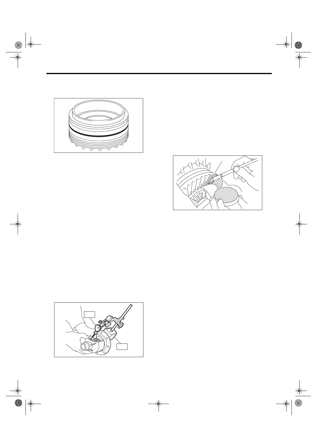
3) Install the O-ring.
NOTE:
Use a new O-ring.
E: INSPECTION
Repair or replace the front differential in following
cases.
• When each gear is damaged, seized, or exces-
sively worn.
• When sliding surfaces of the differential case is
damaged, seized or excessively worn.
• When bearings and bearings part is damaged,
rusted or worn.
• When bearing that fails to turn smoothly or
makes noise when turned.
1. BEVEL PINION GEAR BACKLASH
Measure the bevel pinion gear backlash. If it is not
within specification, install a suitable washer to ad-
just. <Ref. to 6MT-108, ADJUSTMENT, Front Dif-
ferential Assembly.>
NOTE:
• Be sure the pinion gear teeth contact adjacent
gear teeth during measurement.
• Before measuring the backlash, rotate each gear
to get each part accustomed.
ST1
498247001
MAGNET BASE
ST2
498247100
DIAL GAUGE
Standard backlash:
0.13 — 0.18 mm (0.0051 — 0.0071 in)
2. HYPOID GEAR BACKLASH
Check the hypoid gear backlash. If it is not within
specification, adjust it. <Ref. to 6MT-108, HYPOID
GEAR BACKLASH, ADJUSTMENT, Front Differ-
ential Assembly.>
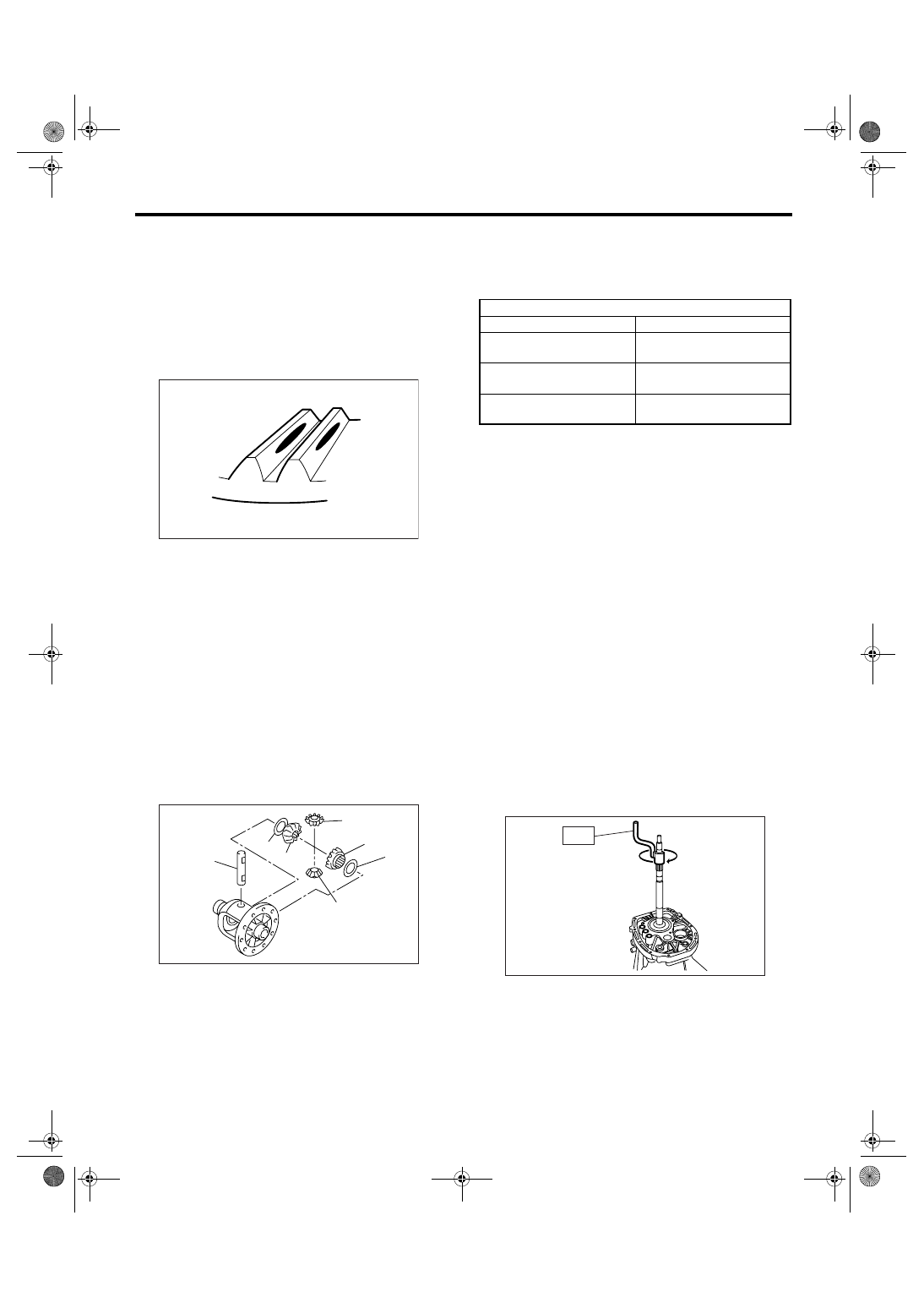
3. TOOTH CONTACT OF HYPOID GEAR
1) Be sure the hypoid gear backlash is within spec-
ification. If it is not within specification, adjust it.
<Ref. to 6MT-108, HYPOID GEAR BACKLASH,
ADJUSTMENT, Front Differential Assembly.>
2) Apply a uniform thin coat of red lead on both
tooth surfaces of three or four teeth of the hypoid
driven gear.
3) Install the drive pinion shaft assembly, and then
secure with four bolts.
NOTE:
Use the old gasket and washer to prevent the mat-
ing surface of housing from damaging.
Tightening torque:
50 N
⋅
m (5.1 kgf-m, 36.9 ft-lb)
4) Rotate the drive pinion shaft to right and left for
several times.
AT-00219
ST1
ST2
MT-00672
MT-00652
6MT-108
MANUAL TRANSMISSION AND DIFFERENTIAL
Front Differential Assembly
5) Remove the drive pinion shaft assembly, and
then check tooth contact. If tooth contact is inaccu-
rate, adjust it. <Ref. to 6MT-99, ADJUSTMENT,
Drive Pinion Shaft Assembly.>
• Correct tooth contact
NOTE:
Under no load, tooth contacts 50 — 60% from cen-
ter to toe side (tooth contact shifts to heel side
when driving).
F: ADJUSTMENT
1. BEVEL PINION GEAR BACKLASH
1) Measure the bevel pinion gear backlash. <Ref.
to 6MT-107, BEVEL PINION GEAR BACKLASH,
INSPECTION, Front Differential Assembly.>
2) Disassemble the differential case. <Ref. to 6MT-
104, DIFFERENTIAL CASE, DISASSEMBLY,
Front Differential Assembly.>
3) Select a washer from the following table, and
then assemble the differential case. <Ref. to 6MT-
106, DIFFERENTIAL CASE, ASSEMBLY, Front
Differential Assembly.>
NOTE:
If the backlash is excessive, select a thicker wash-
er. If the backlash is insufficient, select a thinner
new washer.
2. HYPOID GEAR BACKLASH
1) Install the side retainers of RH and LH side.
ST1
499787000
WRENCH ASSY (RH SIDE)
ST2
18630AA000 WRENCH ASSY (LH SIDE)
NOTE:
Screw in the side retainer of RH side a bit further
than LH side.
2) Install the drive pinion shaft assembly, and then
secure with four bolts.
NOTE:
Use the old gasket and washer to prevent the mat-
ing surface of housing from damaging.
Tightening torque:
50 N
⋅
m (5.1 kgf-m, 36.9 ft-lb)
3) Using the ST, screw in the side retainer LH until
the drive pinion and hypoid driven gear contacts
lightly. Loosen the side retainer RH.
ST1
499787000
WRENCH ASSY (RH SIDE)
ST2
18630AA000 WRENCH ASSY (LH SIDE)
4) Using the ST, rotate the drive pinion shaft sever-
al times.
ST
18631AA000
HANDLE
5) Repeat step 3) and 4) until the side retainer LH
can not be rotated. For the side retainer RH, screw
in until the inner race and outer race contacts light-
ly. This is “0” backlash condition.
(A) Toe side
(B) Heel side
(A) Pinion shaft
(B) Bevel pinion gear
(C) Bevel gear
(D) Washer
AT-00207
(A)
(B)
(A)
(B)
(B)
(C)
(C)
(D)
(D)
MT-00662
Washer
Part No.
Thickness mm (in)
803038021
0.925 — 0.950
(0.0364 — 0.0374)
803038022
0.975 — 1.000
(0.0384 — 0.0394)
803038023
1.025 — 1.050
(0.0404 — 0.0413)
MT-00653
ST
6MT-109
MANUAL TRANSMISSION AND DIFFERENTIAL
Front Differential Assembly
6) Put marks on the engagement position of the
right and left side retainer and clutch housing.
7) Return the side retainer LH for three teeth, and
screw in the side retainer RH for three teeth.
8) Using the ST, secure the drive pinion shaft.
ST
18621AA000
ADAPTER WRENCH
9) Install the SUBARU genuine axle shaft to front
differential LH and RH.
Parts No. 38415AA000 AXLE SHAFT
10) After rotating the drive pinion shaft several
times, measure the hypoid gear backlash using the
ST.
ST1
498255400
PLATE
ST2
498247001
MAGNET BASE
ST3
498247100
DIAL GAUGE
Hypoid gear backlash:
0.13 — 0.18 mm (0.0051 — 0.0071 in)
11) If the backlash is out of specification, adjust it
by turning the right and left side retainers.
12) Screw in the side retainer of RH side for more
than 1.75 teeth.
3. TOOTH CONTACT OF HYPOID GEAR
Refer to the section of drive pinion for checking of
tooth contact. <Ref. to 6MT-107, TOOTH CON-
TACT OF HYPOID GEAR, INSPECTION, Front
Differential Assembly.>
MT-00658
ST
MT-00674
MT-00675
6MT-110
MANUAL TRANSMISSION AND DIFFERENTIAL
Shifter Fork and Rod
24.Shifter Fork and Rod
A: REMOVAL
1) Remove the manual transmission assembly
from vehicle. <Ref. to 6MT-34, REMOVAL, Manual
Transmission Assembly.>
2) Prepare the transmission for overhaul. <Ref. to
6MT-40, Preparation for Overhaul.>
3) Remove the oil pipe, neutral position switch,
back-up light switch and harness. <Ref. to 6MT-42,
REMOVAL, Oil Pipe.> <Ref. to 6MT-45, REMOV-
AL, Neutral Position Switch.> <Ref. to 6MT-43, RE-
MOVAL, Back-up Light Switch.>
4) Remove the extension case. <Ref. to 6MT-47,
REMOVAL, Extension Case.>
5) Remove the transfer driven gear. <Ref. to 6MT-
58, REMOVAL, Transfer Driven Gear.>
6) Remove the center differential. <Ref. to 6MT-60,
REMOVAL, Center Differential.>
7) Remove the oil pump. <Ref. to 6MT-61, RE-
MOVAL, Oil Pump.>
8) Remove the transmission case. <Ref. to 6MT-
64, REMOVAL, Transmission Case.>
9) Remove each gear assembly. <Ref. to 6MT-69,
REMOVAL, Main Shaft Assembly.>
B: INSTALLATION
1) Install each gear assembly at a time. <Ref. to
6MT-70, INSTALLATION, Main Shaft Assembly.>
2) Install the transmission case. <Ref. to 6MT-65,
INSTALLATION, Transmission Case.>
3) Install the oil pump. <Ref. to 6MT-62, INSTAL-
LATION, Oil Pump.>
4) Install the center differential. <Ref. to 6MT-60,
INSTALLATION, Center Differential.>
5) Install the transfer driven gear. <Ref. to 6MT-58,
INSTALLATION, Transfer Driven Gear.>
6) Install the extension case. <Ref. to 6MT-47, IN-
STALLATION, Extension Case.>
7) Install the oil pipe, neutral position switch, back-
up light switch and harness. <Ref. to 6MT-42, IN-
STALLATION, Oil Pipe.> <Ref. to 6MT-45, IN-
STALLATION, Neutral Position Switch.> <Ref. to
6MT-43, INSTALLATION, Back-up Light Switch.>
8) Install the manual transmission assembly into
vehicle. <Ref. to 6MT-36, INSTALLATION, Manual
Transmission Assembly.>
C: DISASSEMBLY
NOTE:
Discard the removed spring pin and replace with a
new one.
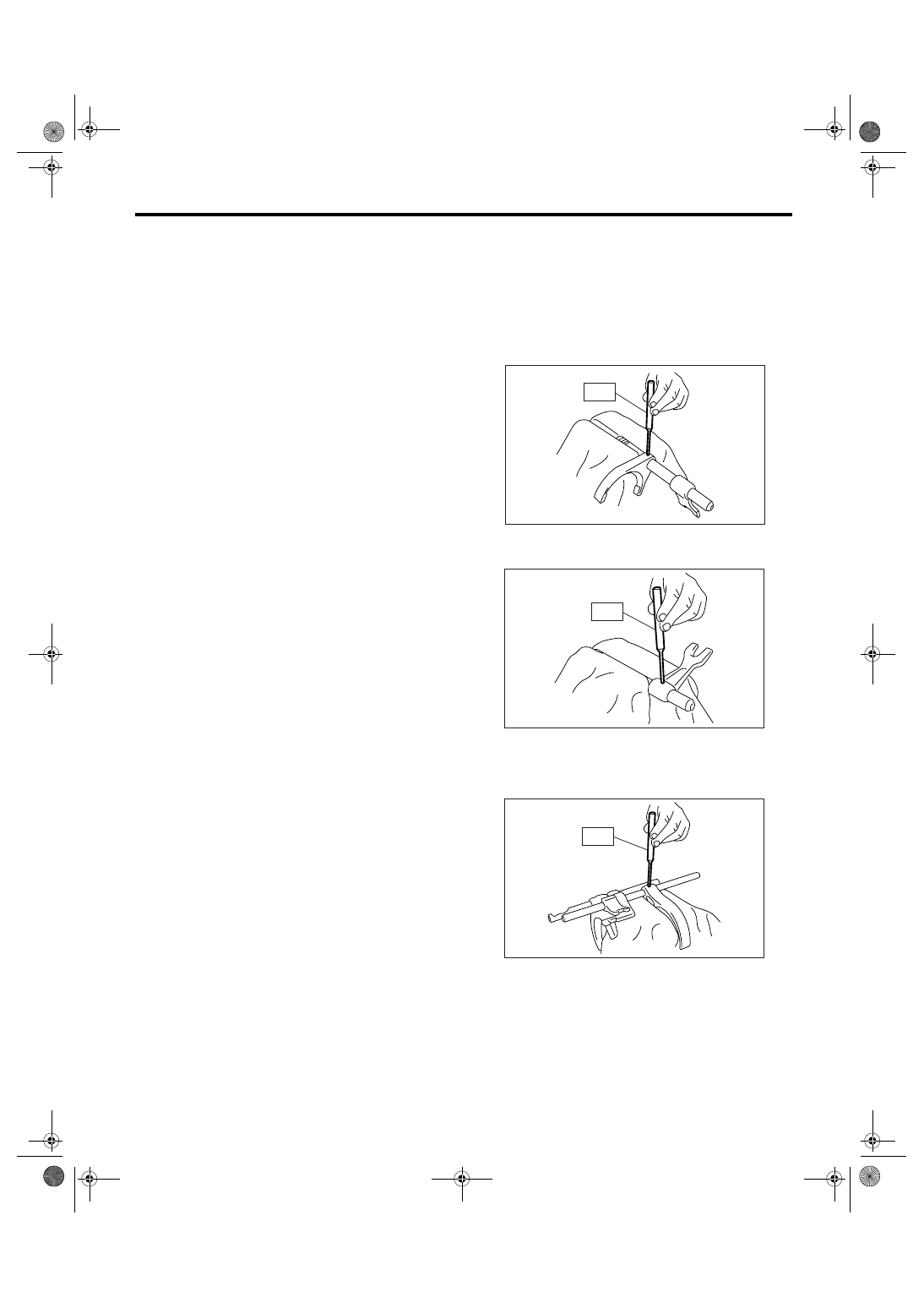
1. REVERSE SHIFTER FORK
1) Using the ST, remove the reverse fork.
ST
398791700
REMOVER
2) Using the ST, remove the reverse shifter arm.
ST
398791700
REMOVER
2. 1ST-2ND, 3RD-4TH SHIFTER FORK
1) Using the ST, remove the 3rd-4th shifter fork.
ST
398791700
REMOVER
MT-00680
ST
MT-00681
ST
MT-00682
ST
Нет комментариевНе стесняйтесь поделиться с нами вашим ценным мнением.
Текст