Subaru Legacy (2005 year). Service manual — part 480
EN(H6DO)(diag)-233
ENGINE (DIAGNOSTICS)
Diagnostic Procedure with Diagnostic Trouble Code (DTC)
CR:DTC P2089 INTAKE CAMSHAFT POSITION ACTUATOR CONTROL CIRCUIT
HIGH (BANK 1)
DTC DETECTING CONDITION:
Immediately at fault recognition
TROUBLE SYMPTOM:
Erroneous idling
CAUTION:
After repair or replacement of faulty parts, conduct Clear Memory Mode <Ref. to EN(H6DO)(diag)-41,
OPERATION, Clear Memory Mode.> and Inspection Mode <Ref. to EN(H6DO)(diag)-34, PROCEDURE,
Inspection Mode.>.
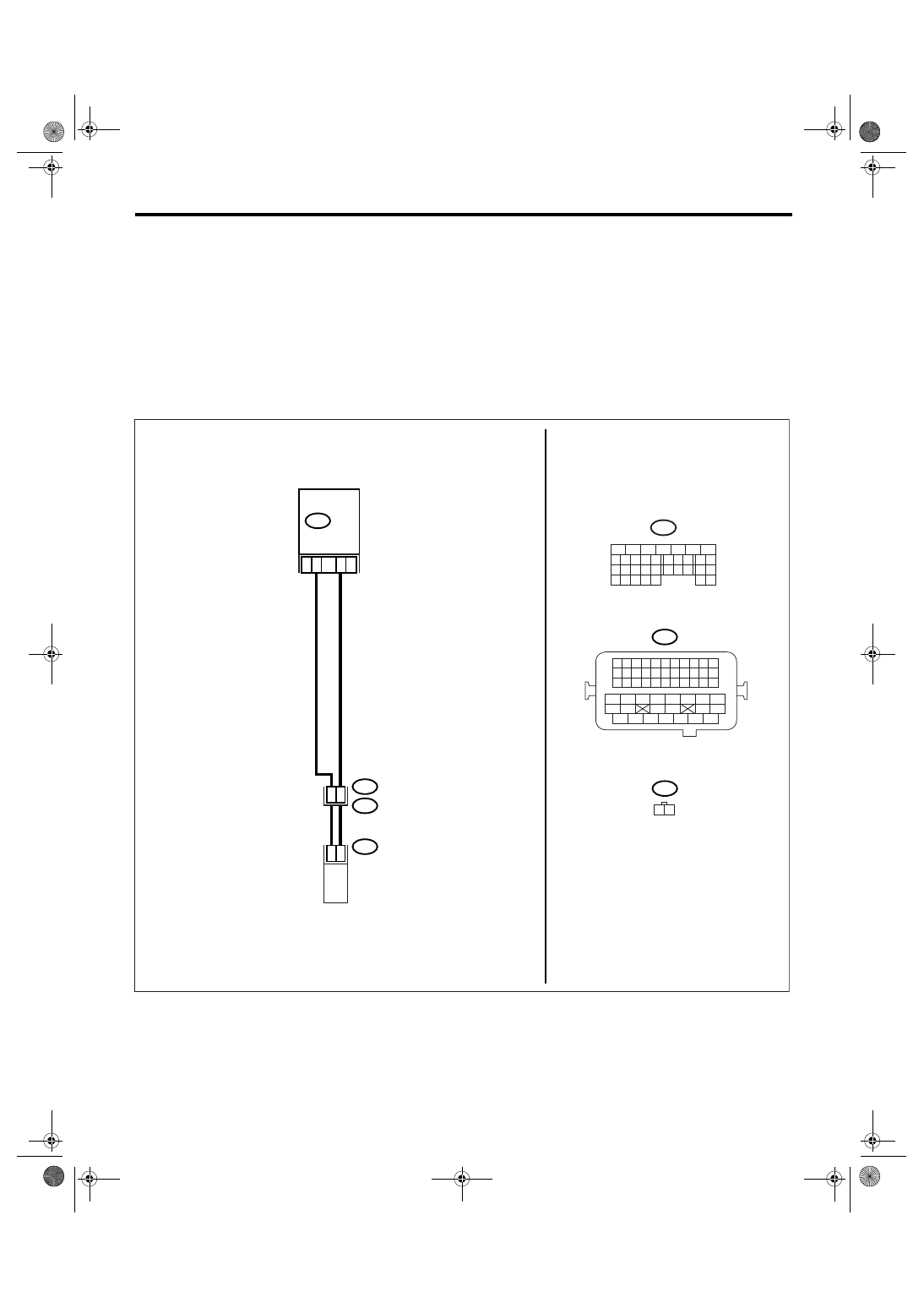
WIRING DIAGRAM:
EN-02514
B21
E2
B134
E67
28
2
1
24
23
E67
B21
1 2
18
B134
5
6
7
8
2
1
9
4
3
10
24
22 23
25
11 12 13 14 15
26 27
28
16 17
18 19 20 21
33 34
29
32
30 31
ECM
OIL FLOW CONTROL
SOLENOID VALVE RH
1 2 3 4
12 13 14 15
5 6 7 8
16 17 18 19
9 10 11
20 21 22
23 24 25 26 27 28 29 30 31 32 33
35
34
37
36
39
38
41
40
43
42
44
45
47
46
49
48
51
50
53
52
54
EN(H6DO)(diag)-234
ENGINE (DIAGNOSTICS)
Diagnostic Procedure with Diagnostic Trouble Code (DTC)
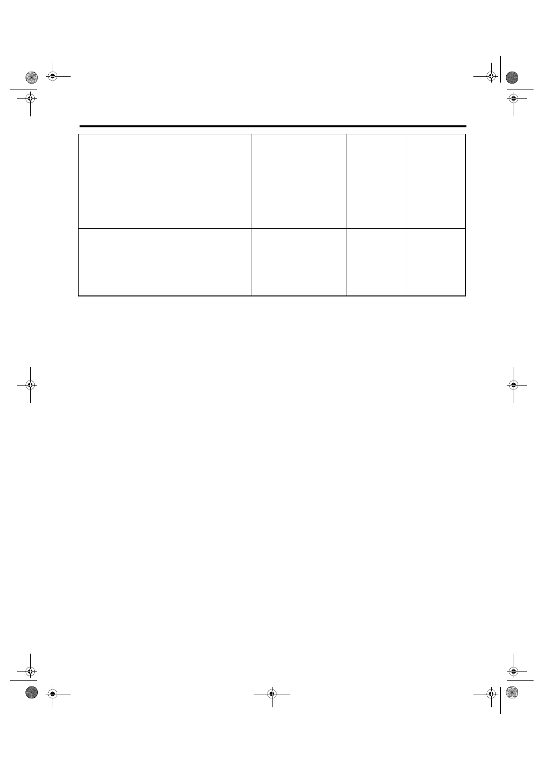
Step
Check
Yes
No
1
CHECK HARNESS BETWEEN ECM AND OIL
FLOW CONTROL SOLENOID VALVE.
1) Turn the ignition switch to OFF.
2) Disconnect the connectors from ECM and
oil flow control solenoid valve.
3) Measure the resistance between oil flow
control solenoid valve and engine ground.
Connector & terminal
(E67) No. 1 — Engine ground:
(E67) No. 2 — Engine ground:
Is the resistance more than 1
M
Ω?
Repair the short
circuit between
ECM and oil flow
control solenoid
valve connector.
2
CHECK OIL FLOW CONTROL SOLENOID
VALVE.
1) Remove the oil flow control solenoid valve
connector.
2) Measure the resistance between oil flow
control solenoid valve terminals.
Terminal
No. 1 — No. 2:
Is the resistance 6 — 12
Ω?
Repair the poor
contact in ECM
and oil flow con-
trol solenoid valve.
Replace the oil
flow control sole-
noid valve. <Ref.
to ME(H6DO)-79,
Oil Flow Control
Solenoid Valve.>
EN(H6DO)(diag)-235
ENGINE (DIAGNOSTICS)
Diagnostic Procedure with Diagnostic Trouble Code (DTC)
CS:DTC P2092 INTAKE CAMSHAFT POSITION ACTUATOR CONTROL CIRCUIT
LOW (BANK 2)
DTC DETECTING CONDITION:
Immediately at fault recognition
TROUBLE SYMPTOM:
Erroneous idling
CAUTION:
After repair or replacement of faulty parts, conduct Clear Memory Mode <Ref. to EN(H6DO)(diag)-41,
OPERATION, Clear Memory Mode.> and Inspection Mode <Ref. to EN(H6DO)(diag)-34, PROCEDURE,
Inspection Mode.>.
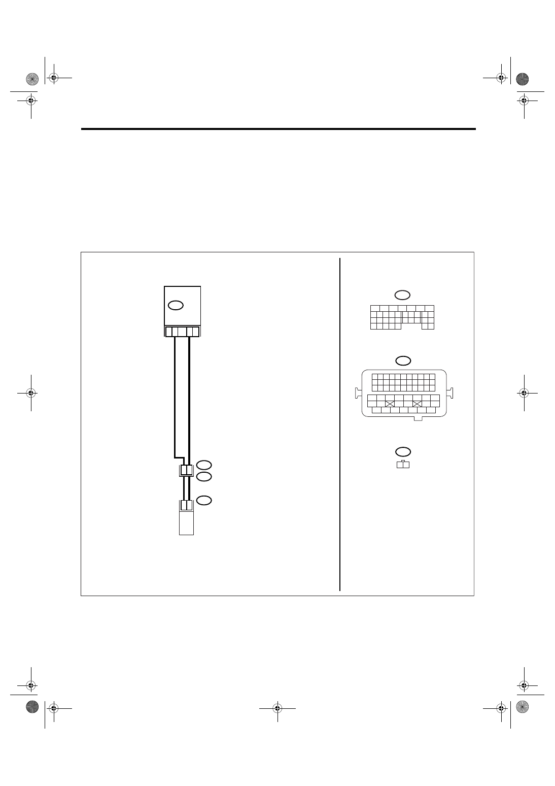
WIRING DIAGRAM:
EN-02515
B21
E2
B134
E68
29
2
1
28
27
E68
B21
1 2
19
B134
5
6
7
8
2
1
9
4
3
10
24
22 23
25
11 12 13 14 15
26 27
28
16 17
18 19 20 21
33 34
29
32
30 31
ECM
1 2 3 4
12 13 14 15
5 6 7 8
16 17 18 19
9 10 11
20 21 22
23 24 25 26 27 28 29 30 31 32 33
35
34
37
36
39
38
41
40
43
42
44
45
47
46
49
48
51
50
53
52
54
OIL FLOW CONTROL
SOLENOID VALVE LH
EN(H6DO)(diag)-236
ENGINE (DIAGNOSTICS)
Diagnostic Procedure with Diagnostic Trouble Code (DTC)
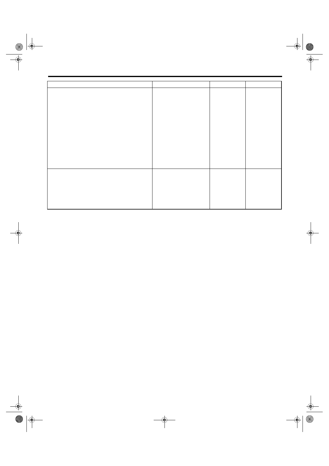
Step
Check
Yes
No
1
CHECK HARNESS BETWEEN ECM AND OIL
FLOW CONTROL SOLENOID VALVE.
1) Turn the ignition switch to OFF.
2) Disconnect the connectors from ECM and
oil flow control solenoid valve.
3) Measure the resistance between ECM and
oil flow control solenoid valve.
Connector & terminal
(B134) No. 19 — (E68) No. 1:
(B134) No. 29 — (E68) No. 2:
Is the resistance less than 1
Ω?
Repair the open
circuit of harness
between ECM and
oil flow control
solenoid valve
connector.
NOTE:
In this case, repair
the following:
• Open circuit of
harness between
ECM and oil flow
control solenoid
valve connector
• Poor contact in
coupling connector
2
CHECK OIL FLOW CONTROL SOLENOID
VALVE.
1) Remove the oil flow control solenoid valve
connector.
2) Measure the resistance between oil flow
control solenoid valve terminals.
Terminal
No. 1 — No. 2:
Is the resistance 6 — 12
Ω?
Repair the poor
contact in ECM
and oil flow con-
trol solenoid valve.
Replace the oil
flow control sole-
noid valve. <Ref.
to ME(H6DO)-79,
Oil Flow Control
Solenoid Valve.>
Нет комментариевНе стесняйтесь поделиться с нами вашим ценным мнением.
Текст