Subaru Legacy (2005 year). Service manual — part 481
EN(H6DO)(diag)-237
ENGINE (DIAGNOSTICS)
Diagnostic Procedure with Diagnostic Trouble Code (DTC)
CT:DTC P2093 INTAKE CAMSHAFT POSITION ACTUATOR CONTROL CIRCUIT
HIGH (BANK 2)
DTC DETECTING CONDITION:
Immediately at fault recognition
TROUBLE SYMPTOM:
Erroneous idling
CAUTION:
After repair or replacement of faulty parts, conduct Clear Memory Mode <Ref. to EN(H6DO)(diag)-41,
OPERATION, Clear Memory Mode.> and Inspection Mode <Ref. to EN(H6DO)(diag)-34, PROCEDURE,
Inspection Mode.>.
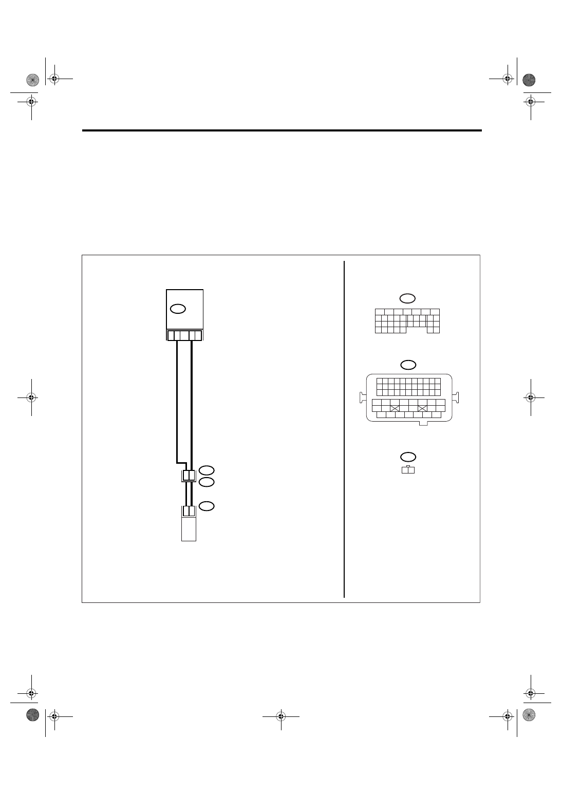
WIRING DIAGRAM:
EN-02515
B21
E2
B134
E68
29
2
1
28
27
E68
B21
1 2
19
B134
5
6
7
8
2
1
9
4
3
10
24
22 23
25
11 12 13 14 15
26 27
28
16 17
18 19 20 21
33 34
29
32
30 31
ECM
1 2 3 4
12 13 14 15
5 6 7 8
16 17 18 19
9 10 11
20 21 22
23 24 25 26 27 28 29 30 31 32 33
35
34
37
36
39
38
41
40
43
42
44
45
47
46
49
48
51
50
53
52
54
OIL FLOW CONTROL
SOLENOID VALVE LH
EN(H6DO)(diag)-238
ENGINE (DIAGNOSTICS)
Diagnostic Procedure with Diagnostic Trouble Code (DTC)
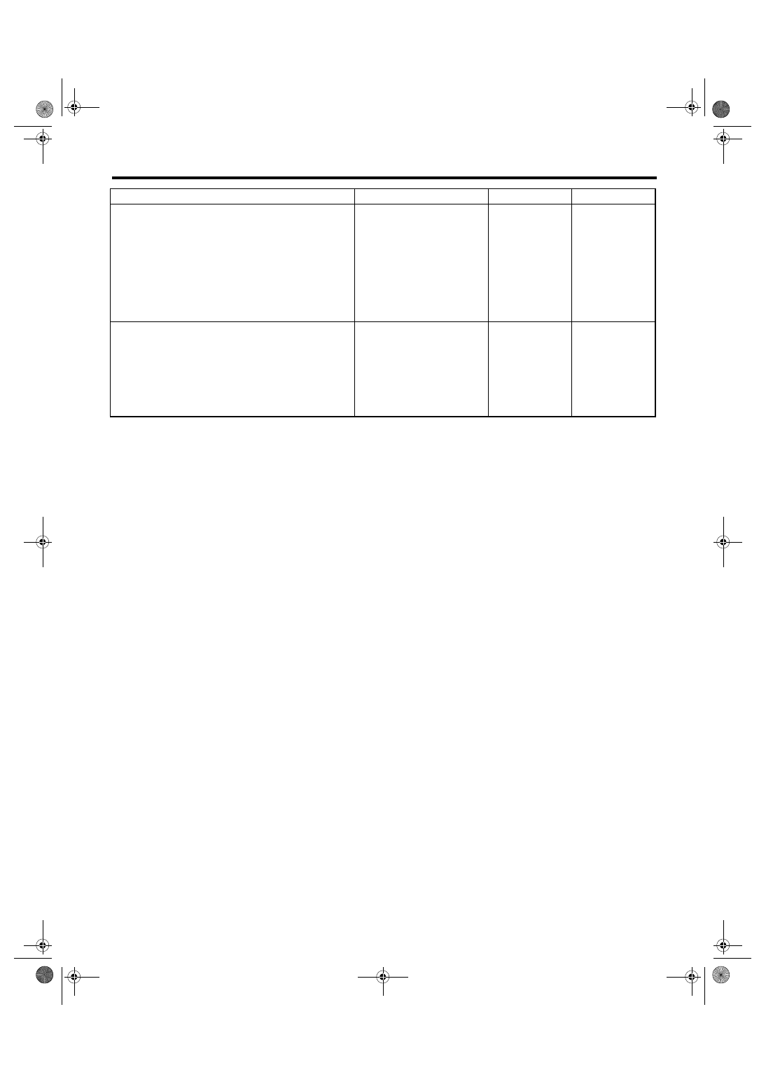
Step
Check
Yes
No
1
CHECK HARNESS BETWEEN ECM AND OIL
FLOW CONTROL SOLENOID VALVE.
1) Turn the ignition switch to OFF.
2) Disconnect the connectors from ECM and
oil flow control solenoid valve.
3) Measure the resistance between oil flow
control solenoid valve and engine ground.
Connector & terminal
(E68) No. 1 — Engine ground:
(E68) No. 2 — Engine ground:
Is the resistance more than 1
M
Ω?
Repair the short
circuit between
ECM and oil flow
control solenoid
valve connector.
2
CHECK OIL FLOW CONTROL SOLENOID
VALVE.
1) Remove the oil flow control solenoid valve
connector.
2) Measure the resistance between oil flow
control solenoid valve terminals.
Terminal
No. 1 — No. 2:
Is the resistance 6 — 12
Ω?
Repair the poor
contact in ECM
and oil flow con-
trol solenoid valve.
Replace the oil
flow control sole-
noid valve. <Ref.
to ME(H6DO)-79,
Oil Flow Control
Solenoid Valve.>
EN(H6DO)(diag)-239
ENGINE (DIAGNOSTICS)
Diagnostic Procedure with Diagnostic Trouble Code (DTC)
CU:DTC P2101 THROTTLE ACTUATOR CONTROL MOTOR CIRCUIT RANGE/
PERFORMANCE
DTC DETECTING CONDITION:
Immediately at fault recognition
TROUBLE SYMPTOM:
• Erroneous idling
• Poor driving performance
• Engine stalls.
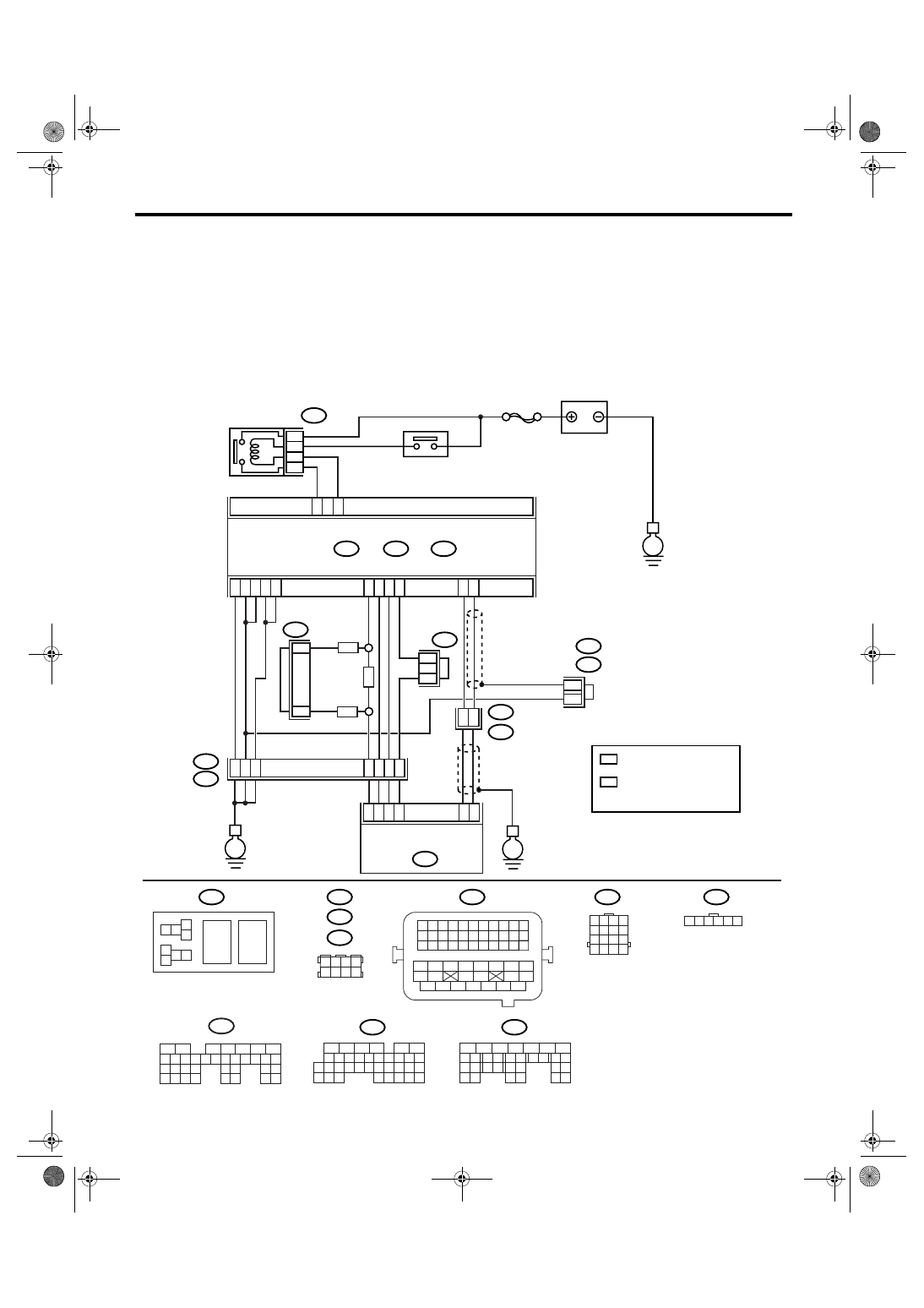
WIRING DIAGRAM:
EN-03499
SBF-7
B135
B:
B137
B136
D:
B362
E1
B20
B83
B122
C:
E
E
E
D6
B35
38
39
20
19
16
15
*
*
E2
B21
E57
4
6
1
2
3
5
D4
D5
C35
C16
B1
B4
D1
D2
D3
36
35
37
C29
C18
ECM
5
6
B362
B20
B21
E57
B122
B83
B138
1 2
7 8
3
4
5
6
1 2 3 4 5 6 7 8 9 10 11
12 13 14 15 16 17 18 19 20 21 22
23 24 25
34 35
36 37 38 39 40 41
48 49
50 51 52 53 54
42 43
44 45
46 47
26 27 28 29 30 31 32 33
1 2 3 4
5 6 7 8
1
2
7
8 9
5
6
3
4
10 11 12
19 20 21
29
30 31
13 14 15 16 17
27
28
18
22 23
24 25
26
1
2
8 9
5
6
3
4
10 11 12
19 20 21
29 30
31
13 14 15 16
17
27
28
18
22 23 24 25 26
7
32 33 34 35
B136
C:
B137
D:
BATTERY
MAIN RELAY
ELECTRONIC
THROTTLE
CONTROL RELAY
ELECTRONIC
THROTTLE CONTROL
1 2 3 4
5 6 7 8
9 10 11 12
13 14 15 16
1 2 3 4 5 6
*
*
1
*
2
*
2
1
1
1
*
1 : TERMINAL No.
RANDOM ARRANGEMENT
B135
5
6
7
8
2
1
9
4
3
10
24
22 23
25
11 12 13 14 15
26 27
28
16 17 18 19
20 21
29 30 31
32 33
34 35
B:
8
7
RHD
RHD
LHD
*
: TERMINAL No.
RANDOM ARRANGEMENT
AMONG 3,4,7, AND 8
2
B122
B138
: LHD
: RHD

EN(H6DO)(diag)-240
ENGINE (DIAGNOSTICS)
Diagnostic Procedure with Diagnostic Trouble Code (DTC)
Step
Check
Yes
No
1
CHECK ELECTRONIC THROTTLE CON-
TROL RELAY.
1) Turn the ignition switch to OFF.
2) Remove the electronic throttle control relay.
3) Connect the battery to electronic throttle
control relay terminals No. 5 and No. 6.
4) Measure the resistance between electronic
throttle control relay terminals.
Terminal
No. 7 — No. 8:
Is the resistance less than 1
Ω?
Replace the elec-
tronic throttle con-
trol relay.
2
CHECK POWER SUPPLY OF ELECTRONIC
THROTTLE CONTROL RELAY.
1) Turn the ignition switch to ON.
2) Measure the voltage between electronic
throttle control relay connector and chassis
ground.
Connector & terminal
(B362) No. 5 (+) — Chassis ground (
−
):
(B362) No. 8 (+) — Chassis ground (
−
):
Is the voltage more than 10 V? Go to step 3.
Repair the open or
ground short cir-
cuit of power sup-
ply circuit.
3
CHECK HARNESS BETWEEN ECM AND
ELECTRONIC THROTTLE CONTROL RE-
LAY.
1) Turn the ignition switch to OFF.
2) Disconnect the connector from ECM.
3) Turn the ignition switch to ON.
4) Measure the voltage between electronic
throttle control relay connector and chassis
ground.
Connector & terminal
(B362) No. 6 (+) — Chassis ground (
−
):
Is the voltage more than 10 V? Repair the power
supply short cir-
cuit of harness
between ECM and
electronic throttle
control.
4
CHECK HARNESS BETWEEN ECM AND
ELECTRONIC THROTTLE CONTROL RE-
LAY.
1) Turn the ignition switch to OFF.
2) Measure the resistance between electronic
throttle control relay connector and chassis
ground.
Connector & terminal
(B362) No. 6 — Chassis ground:
(B362) No. 7 — Chassis ground:
Is the resistance more than 1
M
Ω?
Repair the ground
short circuit of har-
ness between
ECM and elec-
tronic throttle con-
trol relay.
5
CHECK HARNESS BETWEEN ECM AND
ELECTRONIC THROTTLE CONTROL RE-
LAY.
Measure the resistance between ECM connec-
tor and electronic throttle control relay connec-
tor.
Connector & terminal
(B135) No. 35 — (B362) No. 6:
(B137) No. 6 — (B362) No. 7:
Is the resistance less than 1
Ω?
Repair the open
circuit of harness
between ECM and
electronic throttle
control relay.
6
CHECK SENSOR OUTPUT.
1) Connect all the connectors.
2) Turn the ignition switch to ON.
3) Read the data of main throttle sensor signal
using Subaru Select Monitor.
NOTE:
For detailed operation procedure, refer to
“READ CURRENT DATA FOR ENGINE”. <Ref.
to EN(H6DO)(diag)-26, Subaru Select Moni-
tor.>
Is the voltage more than 0.4 V? Go to step 7.
Нет комментариевНе стесняйтесь поделиться с нами вашим ценным мнением.
Текст