Subaru Legacy (2005 year). Service manual — part 465

EN(H6DO)(diag)-173
ENGINE (DIAGNOSTICS)
Diagnostic Procedure with Diagnostic Trouble Code (DTC)
Step
Check
Yes
No
1
CHECK SENSOR OUTPUT.
1) Turn the ignition switch to ON.
2) Read the data of sub throttle sensor signal
using Subaru Select Monitor.
NOTE:
For detailed operation procedure, refer to
“READ CURRENT DATA FOR ENGINE”. <Ref.
to EN(H6DO)(diag)-26, Subaru Select Moni-
tor.>
Is the voltage more than 0.8 V? Go to step 2.
2
CHECK POOR CONTACT.
Check poor contact in connector between
ECM and electronic throttle control.
Is there poor contact?
Repair the poor
contact.
Temporary poor
contact occurred,
but it is normal at
present.
3
CHECK HARNESS BETWEEN ECM AND
ELECTRONIC THROTTLE CONTROL.
1) Turn the ignition switch to OFF.
2) Disconnect the connector from ECM.
3) Disconnect the connectors from electronic
throttle control.
4) Measure the resistance between ECM con-
nector and electronic throttle control connector.
Connector & terminal
(B136) No. 29 — (E57) No. 4:
(B136) No. 16 — (E57) No. 5:
Is the resistance less than 1
Ω?
Repair the open
circuit of harness
connector.
4
CHECK HARNESS BETWEEN ECM AND
ELECTRONIC THROTTLE CONTROL.
Measure the resistance between ECM connec-
tor and chassis ground.
Connector & terminal
(B136) No. 29 — Chassis ground:
(B136) No. 16 — Chassis ground:
Is the resistance more than 1
M
Ω?
Repair the chas-
sis short circuit of
harness.
5
CHECK SENSOR POWER SUPPLY.
1) Connect the ECM connector.
2) Turn the ignition switch to ON.
3) Measure the voltage between electronic
throttle control connector and engine ground.
Connector & terminal
(E57) No. 5 (+) — Engine ground (
−
):
Is the voltage 4.5 — 5.5 V?
Repair the poor
contact in ECM
connector.
Replace the ECM
if defective. <Ref.
to FU(H6DO)-34,
Engine Control
Module (ECM).>
6
CHECK SHORT CIRCUIT INSIDE THE ECM.
1) Turn the ignition switch to OFF.
2) Measure the resistance between electronic
throttle control connector and engine ground.
Connector & terminal
(E57) No. 4 — Engine ground:
Is the resistance more than 10
Ω?
Repair the poor
contact of elec-
tronic throttle con-
trol connector.
Replace the elec-
tronic throttle con-
trol if defective.
Repair the poor
contact in ECM
connector.
Replace the ECM
if defective. <Ref.
to FU(H6DO)-34,
Engine Control
Module (ECM).>
EN(H6DO)(diag)-174
ENGINE (DIAGNOSTICS)
Diagnostic Procedure with Diagnostic Trouble Code (DTC)
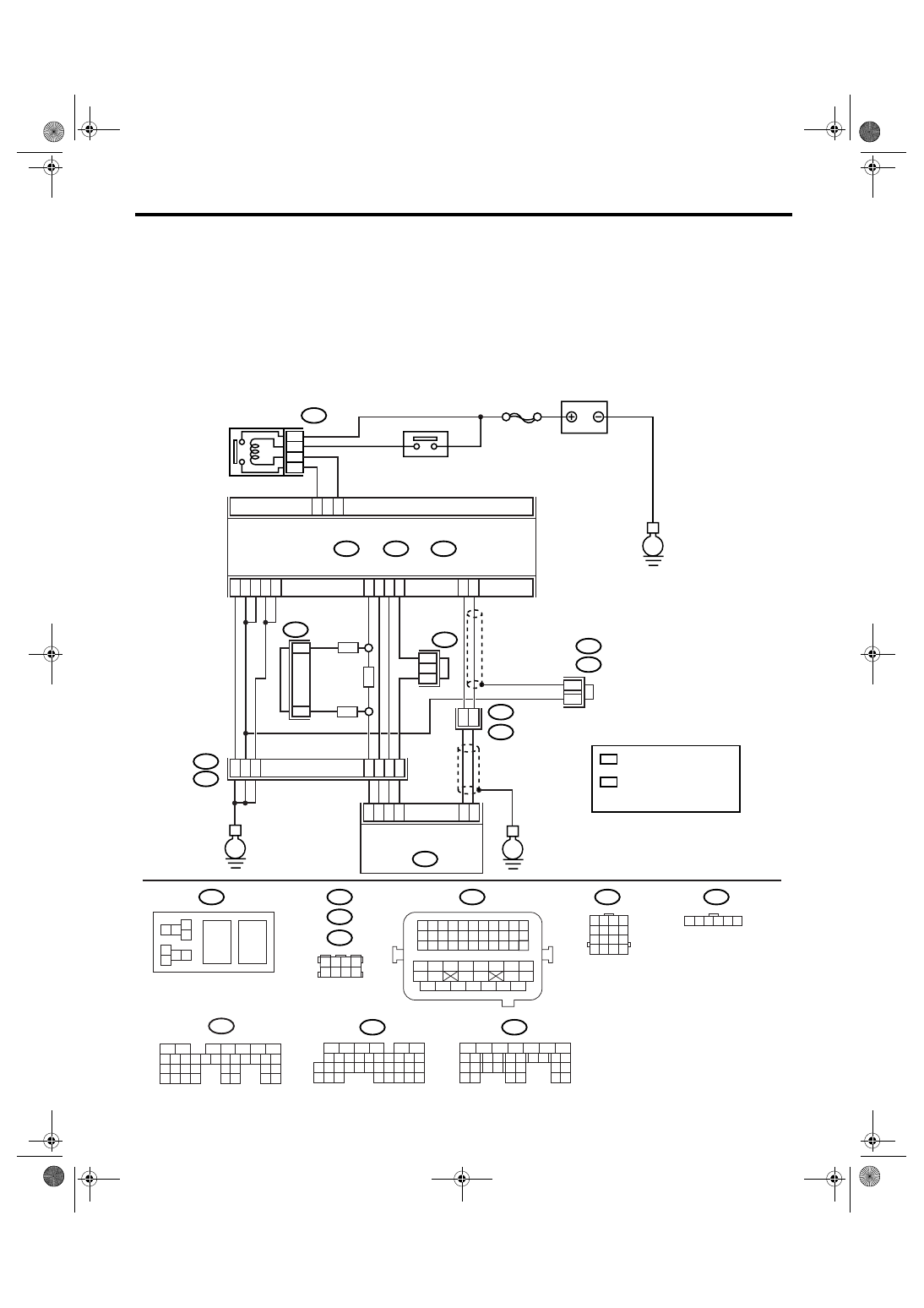
AX:DTC P0223 THROTTLE/PEDAL POSITION SENSOR/SWITCH “B” CIRCUIT
HIGH
DTC DETECTING CONDITION:
Immediately at fault recognition
TROUBLE SYMPTOM:
• Erroneous idling
• Poor driving performance
• Engine stalls.
WIRING DIAGRAM:
EN-03499
SBF-7
B135
B:
B137
B136
D:
B362
E1
B20
B83
B122
C:
E
E
E
D6
B35
38
39
20
19
16
15
*
*
E2
B21
E57
4
6
1
2
3
5
D4
D5
C35
C16
B1
B4
D1
D2
D3
36
35
37
C29
C18
ECM
5
6
B362
B20
B21
E57
B122
B83
B138
1 2
7 8
3
4
5
6
1 2 3 4 5 6 7 8 9 10 11
12 13 14 15 16 17 18 19 20 21 22
23 24 25
34 35
36 37 38 39 40 41
48 49
50 51 52 53 54
42 43
44 45
46 47
26 27 28 29 30 31 32 33
1 2 3 4
5 6 7 8
1
2
7
8 9
5
6
3
4
10 11 12
19 20 21
29
30 31
13 14 15 16 17
27
28
18
22 23
24 25
26
1
2
8 9
5
6
3
4
10 11 12
19 20 21
29 30
31
13 14 15 16
17
27
28
18
22 23 24 25 26
7
32 33 34 35
B136
C:
B137
D:
BATTERY
MAIN RELAY
ELECTRONIC
THROTTLE
CONTROL RELAY
ELECTRONIC
THROTTLE CONTROL
1 2 3 4
5 6 7 8
9 10 11 12
13 14 15 16
1 2 3 4 5 6
*
*
1
*
2
*
2
1
1
1
*
1 : TERMINAL No.
RANDOM ARRANGEMENT
B135
5
6
7
8
2
1
9
4
3
10
24
22 23
25
11 12 13 14 15
26 27
28
16 17 18 19
20 21
29 30 31
32 33
34 35
B:
8
7
RHD
RHD
LHD
*
: TERMINAL No.
RANDOM ARRANGEMENT
AMONG 3,4,7, AND 8
2
B122
B138
: LHD
: RHD

EN(H6DO)(diag)-175
ENGINE (DIAGNOSTICS)
Diagnostic Procedure with Diagnostic Trouble Code (DTC)
Step
Check
Yes
No
1
CHECK SENSOR OUTPUT.
1) Turn the ignition switch to ON.
2) Read the data of sub throttle sensor signal
using Subaru Select Monitor.
NOTE:
For detailed operation procedure, refer to
“READ CURRENT DATA FOR ENGINE”. <Ref.
to EN(H6DO)(diag)-26, Subaru Select Moni-
tor.>
Is the voltage less than 4.73
V?
2
CHECK POOR CONTACT.
Check poor contact in connector between
ECM and electronic throttle control.
Is there poor contact in con-
nector between ECM and elec-
tronic throttle control?
Repair the poor
contact.
Temporary poor
contact occurred,
but it is normal at
present.
3
CHECK HARNESS BETWEEN ECM AND
ELECTRONIC THROTTLE CONTROL.
1) Turn the ignition switch to OFF.
2) Disconnect the connector from ECM.
3) Disconnect the connectors from electronic
throttle control.
4) Measure the resistance between ECM con-
nector and electronic throttle control connector.
Connector & terminal
(B136) No. 35 — (E57) No. 3:
(B136) No. 29 — (E57) No. 4:
Is the resistance less than 1
Ω?
Repair the open
circuit of harness
connector.
4
CHECK HARNESS BETWEEN ECM AND
ELECTRONIC THROTTLE CONTROL.
1) Connect the ECM connector.
2) Measure the resistance between electronic
throttle control connector and engine ground.
Connector & terminal
(E57) No. 3 — Engine ground:
Is the resistance less than 5
Ω?
Repair the poor
contact in ECM
connector.
Replace the ECM
if defective. <Ref.
to FU(H6DO)-34,
Engine Control
Module (ECM).>
5
CHECK HARNESS BETWEEN ECM AND
ELECTRONIC THROTTLE CONTROL.
Measure the voltage between electronic throt-
tle control connector and engine ground.
Connector & terminal
(E57) No. 4 (+) — Engine ground (
−
):
Is the voltage less than 10 V?
Repair the battery
short circuit of har-
ness between
ECM connector
and electronic
throttle control
connector.
6
CHECK HARNESS BETWEEN ECM AND
ELECTRONIC THROTTLE CONTROL.
1) Turn the ignition switch to OFF.
2) Disconnect the connector from ECM.
3) Measure the resistance between connector
terminals.
Connector & terminal
(B136) No. 29 — (B136) No. 16:
Is the resistance more than 1
M
Ω?
Repair the poor
contact. Repair the
electronic throttle
control.
Sensor power sup-
ply circuit may be
shorted.
EN(H6DO)(diag)-176
ENGINE (DIAGNOSTICS)
Diagnostic Procedure with Diagnostic Trouble Code (DTC)
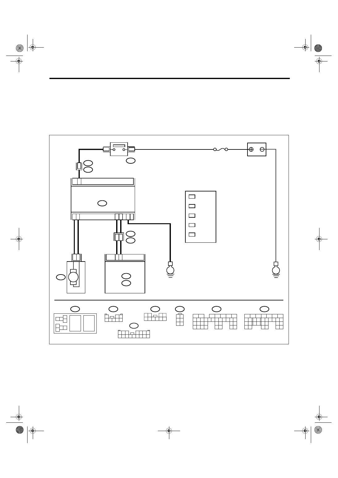
AY:DTC P0230 FUEL PUMP PRIMARY CIRCUIT
DTC DETECTING CONDITION:
Detects when malfunction occurs in 2 continuous driving cycles.
CAUTION:
After repair or replacement of faulty parts, conduct Clear Memory Mode <Ref. to EN(H6DO)(diag)-41,
OPERATION, Clear Memory Mode.> and Inspection Mode <Ref. to EN(H6DO)(diag)-34, PROCEDURE,
Inspection Mode.>.
WIRING DIAGRAM:
EN-03492
E
E
M
10
7
6
5
6
No.11
B362
R122
B135
B:
B137
D:
R58
7
D28
B27
1
2
9
8
5
FUEL PUMP
CONTROL UNIT
FUEL
PUMP
ECM
BATTERY
FUEL PUMP
RELAY
R58
2
5
4
6
1
3
B135
B:
5
6
7
8
2
1
9
4
3
10
24
22 23
25
11 12 13 14 15
26 27
28
16 17 18 19
20 21
29 30 31
32 33
34 35
B137
D:
5
6
7
8
2
1
9
4
3
10
22 23
11 12 13 14 15
24 25
26
16 17
18 19 20 21
27
28 29
30 31
R122
3 4
1 2
5
8 9 10
6 7
B98
1
2 3
4 5 6 7 8
B362
5
6
7 8
3
4
1 2
B97
1 2 3
4 5 6 7
8 9 10 11 12 13 14 15 16
*
LHD: 16
RHD: 4
1
*
LHD: B97
RHD: B98
2
*
3
*
2
*
5
*
4
*
1
*
2
*
3
*
LHD: R1
RHD: R2
3
*
LHD: 6
RHD: 5
4
*
LHD: 15
RHD: 6
5
Нет комментариевНе стесняйтесь поделиться с нами вашим ценным мнением.
Текст