Subaru Legacy (2005 year). Service manual — part 466
EN(H6DO)(diag)-177
ENGINE (DIAGNOSTICS)
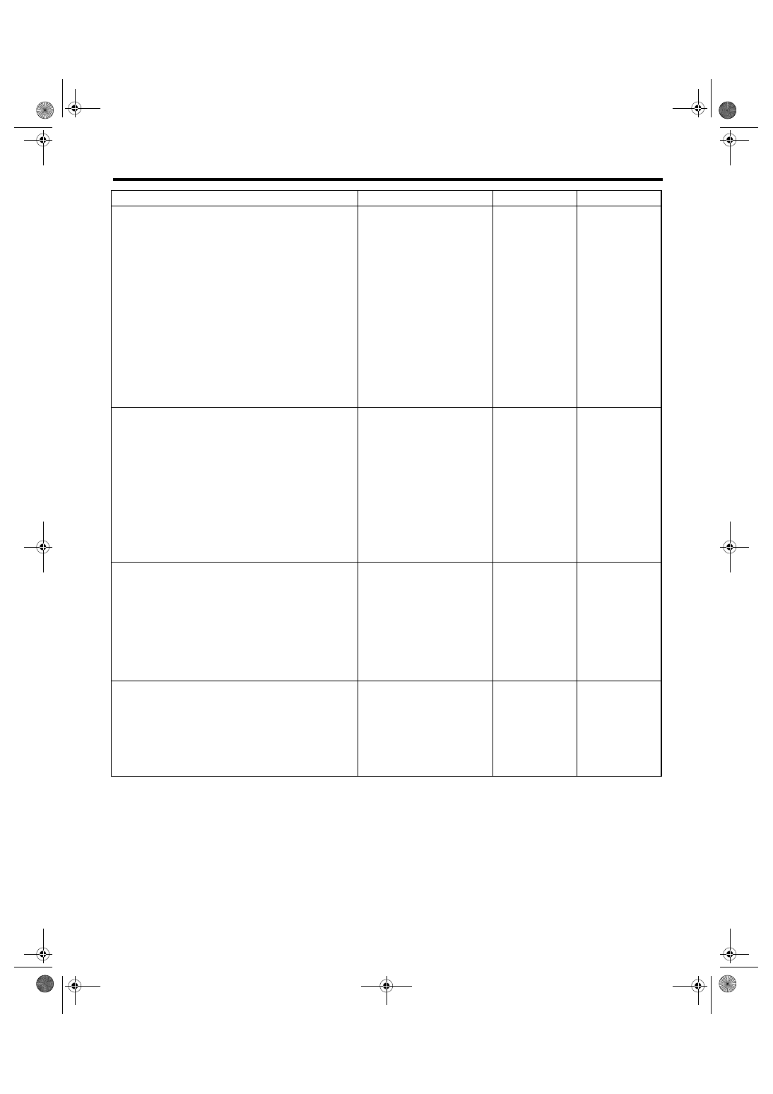
Diagnostic Procedure with Diagnostic Trouble Code (DTC)
Step
Check
Yes
No
1
CHECK POWER SUPPLY CIRCUIT TO FUEL
PUMP CONTROL UNIT.
1) Turn the ignition switch to OFF.
2) Disconnect the connector from fuel pump
control unit.
3) Turn the ignition switch to ON.
4) Measure the voltage between fuel pump
control unit and chassis ground.
Connector & terminal
(R122) No. 10 (+) — Chassis ground (
−
):
Is the voltage more than 10 V? Go to step 2.
Repair the power
supply circuit.
NOTE:
In this case, repair
the following:
• Open or ground
short circuit of har-
ness between fuel
pump relay and
fuel pump control
unit
• Poor contact in
fuel pump control
unit connector
• Poor contact in
fuel pump relay
connector
2
CHECK GROUND CIRCUIT OF FUEL PUMP
CONTROL UNIT.
1) Turn the ignition switch to OFF.
2) Measure the resistance of harness
between fuel pump control unit and chassis
ground.
Connector & terminal
(R122) No. 5 — Chassis ground:
Is the resistance less than 5
Ω?
Repair the har-
ness and connec-
tor.
NOTE:
In this case, repair
the following:
• Open circuit
between fuel pump
control unit and
chassis ground
• Poor contact in
fuel pump control
unit connector
3
CHECK HARNESS BETWEEN FUEL PUMP
CONTROL UNIT AND FUEL PUMP CONNEC-
TOR.
1) Disconnect the connector from fuel pump.
2) Measure the resistance of harness
between fuel pump control unit and fuel pump
connector.
Connector & terminal
(R122) No. 7 — (R58) No. 5:
(R122) No. 6 — (R58) No. 6:
Is the resistance less than 1
Ω?
Repair the open
circuit between
fuel pump control
unit and fuel
pump.
4
CHECK HARNESS BETWEEN FUEL PUMP
CONTROL UNIT AND FUEL PUMP CONNEC-
TOR.
Measure the resistance of harness between
fuel pump control unit and chassis ground.
Connector & terminal
(R122) No. 7 — Chassis ground:
(R122) No. 6 — Chassis ground:
Is the resistance more than 1
M
Ω?
Repair the ground
short circuit
between fuel pump
control unit and
fuel pump.
EN(H6DO)(diag)-178
ENGINE (DIAGNOSTICS)
Diagnostic Procedure with Diagnostic Trouble Code (DTC)
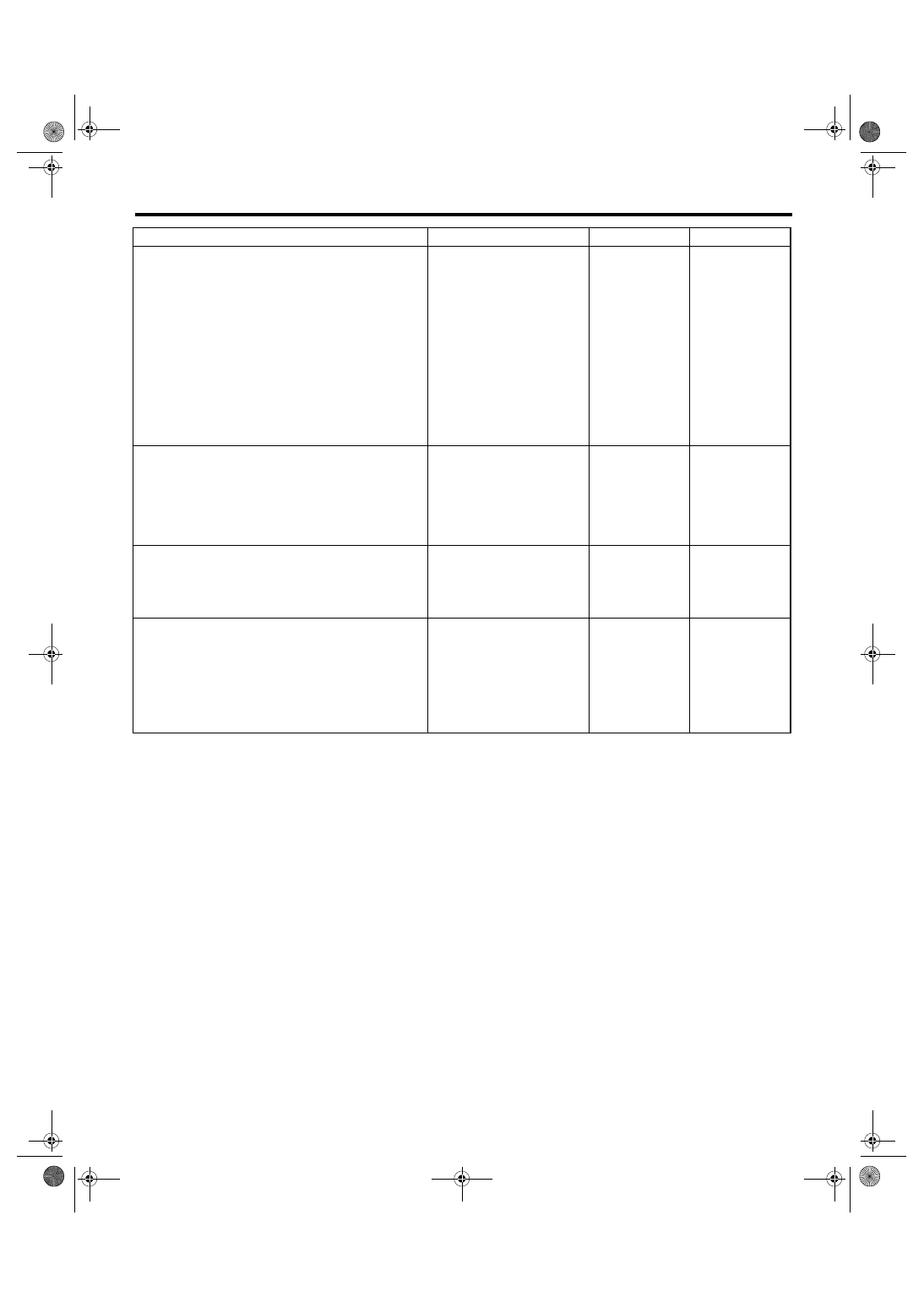
5
CHECK HARNESS BETWEEN FUEL PUMP
CONTROL UNIT AND ECM CONNECTOR.
1) Turn the ignition switch to OFF.
2) Disconnect the connector from ECM.
3) Measure the resistance of harness
between fuel pump control unit and ECM con-
nector.
Connector & terminal
(R122) No. 9 — (B137) No. 28:
(R122) No. 8 — (B135) No. 27:
Is the resistance less than 1
Ω?
Repair the har-
ness and connec-
tor.
NOTE:
In this case, repair
the following:
• Open circuit
between fuel pump
control unit and
ECM
• Poor contact in
fuel pump control
unit and ECM con-
nector
6
CHECK HARNESS BETWEEN FUEL PUMP
CONTROL UNIT AND ECM CONNECTOR.
Measure the resistance of harness between
fuel pump control unit and chassis ground.
Connector & terminal
(R122) No. 9 — Chassis ground:
(R122) No. 8 — Chassis ground:
Is the resistance more than 1
M
Ω?
Repair the ground
short circuit
between fuel pump
control unit and
ECM.
7
CHECK POOR CONTACT.
Check poor contact in ECM and fuel pump
control unit connector.
Is there poor contact in ECM
and fuel pump control unit con-
nector?
Repair the poor
contact in ECM
and fuel pump
control unit con-
nector.
8
CHECK EXPERIENCE OF RUNNING OUT OF
FUEL.
Has the vehicle experience
running out of fuel?
Finish the diagno-
sis.
NOTE:
DTC may be re-
corded as a result
of fuel pump idling
while running out
of fuel.
Replace the fuel
pump control unit.
<Ref. to
FU(H6DO)-38,
Fuel Pump Control
Unit.>
Step
Check
Yes
No
EN(H6DO)(diag)-179
ENGINE (DIAGNOSTICS)
Diagnostic Procedure with Diagnostic Trouble Code (DTC)
AZ:DTC P0301 CYLINDER 1 MISFIRE DETECTED
NOTE:
For the diagnostic procedure, refer to DTC P0306. <Ref. to EN(H6DO)(diag)-180, DTC P0306 CYLINDER 6
MISFIRE DETECTED, Diagnostic Procedure with Diagnostic Trouble Code (DTC).>
BA:DTC P0302 CYLINDER 2 MISFIRE DETECTED
NOTE:
For the diagnostic procedure, refer to DTC P0306. <Ref. to EN(H6DO)(diag)-180, DTC P0306 CYLINDER 6
MISFIRE DETECTED, Diagnostic Procedure with Diagnostic Trouble Code (DTC).>
BB:DTC P0303 CYLINDER 3 MISFIRE DETECTED
NOTE:
For the diagnostic procedure, refer to DTC P0306. <Ref. to EN(H6DO)(diag)-180, DTC P0306 CYLINDER 6
MISFIRE DETECTED, Diagnostic Procedure with Diagnostic Trouble Code (DTC).>
BC:DTC P0304 CYLINDER 4 MISFIRE DETECTED
NOTE:
For the diagnostic procedure, refer to DTC P0306. <Ref. to EN(H6DO)(diag)-180, DTC P0306 CYLINDER 6
MISFIRE DETECTED, Diagnostic Procedure with Diagnostic Trouble Code (DTC).>
BD:DTC P0305 CYLINDER 5 MISFIRE DETECTED
NOTE:
For the diagnostic procedure, refer to DTC P0306. <Ref. to EN(H6DO)(diag)-180, DTC P0306 CYLINDER 6
MISFIRE DETECTED, Diagnostic Procedure with Diagnostic Trouble Code (DTC).>
EN(H6DO)(diag)-180
ENGINE (DIAGNOSTICS)
Diagnostic Procedure with Diagnostic Trouble Code (DTC)
BE:DTC P0306 CYLINDER 6 MISFIRE DETECTED
DTC DETECTING CONDITION:
• Detects when malfunction occurs in 2 continuous driving cycles.
• Immediately at fault recognition (A misfire which could damage catalyst occurs.)
TROUBLE SYMPTOM:
• Engine stalls.
• Erroneous idling
• Rough driving
CAUTION:
After repair or replacement of faulty parts, conduct Clear Memory Mode <Ref. to EN(H6DO)(diag)-41,
OPERATION, Clear Memory Mode.> and Inspection Mode <Ref. to EN(H6DO)(diag)-34, PROCEDURE,
Inspection Mode.>.
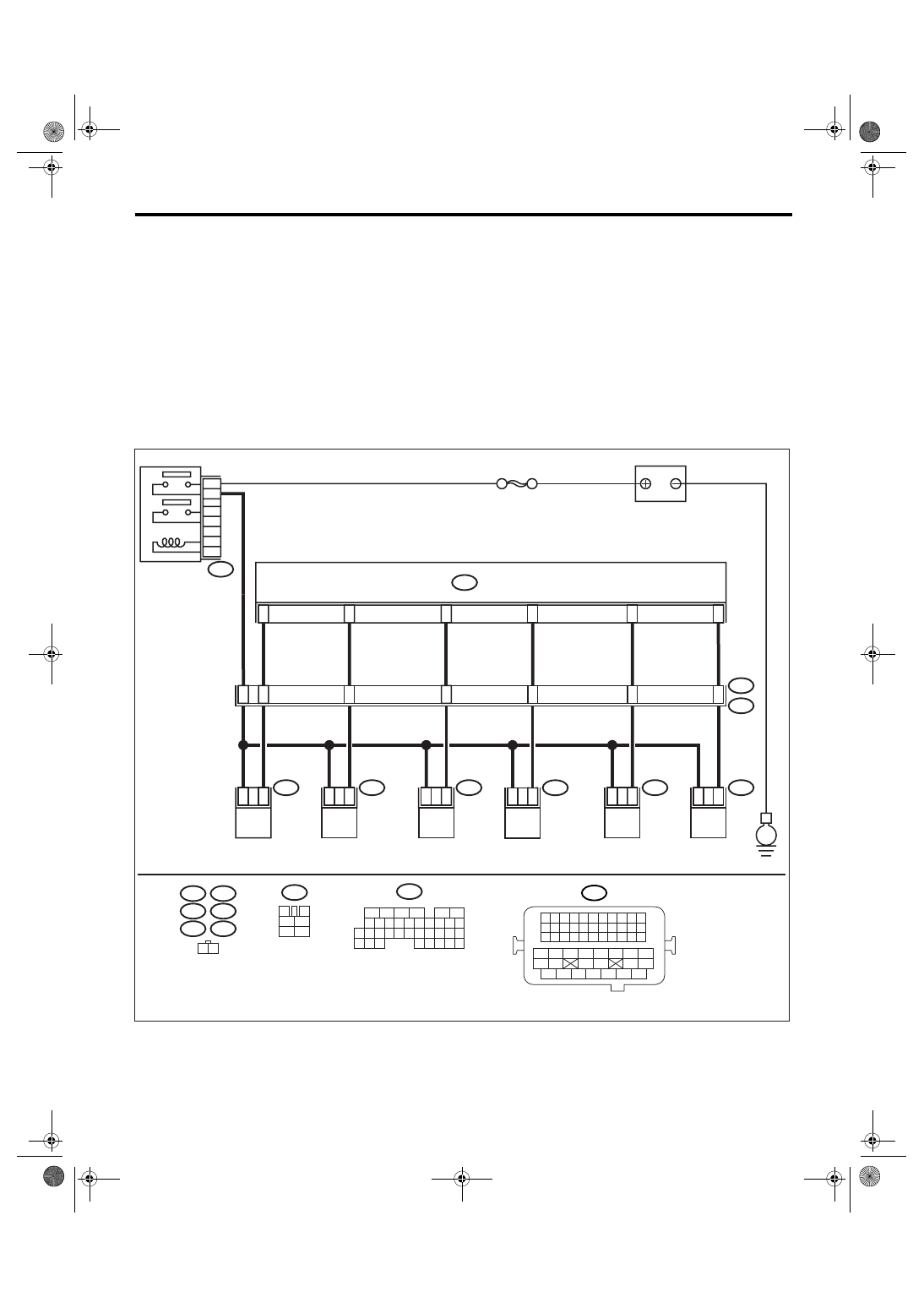
WIRING DIAGRAM:
E6
E17
E5
E16
E43
E44
1
2
1
2
1
2
1
2
4
5
6
3
42
48
43
44
45
ECM
B136
E5
E16
E6
E17
B21
E2
FUEL INJECTOR
No. 1
FUEL INJECTOR
No. 2
FUEL INJECTOR
No. 3
FUEL INJECTOR
No. 4
BATTERY
1
2
1
2
2
1
46
47
E43
E44
FUEL INJECTOR
No. 5
FUEL INJECTOR
No. 6
SBF-7
B47
MAIN RELAY
B47
3
4
1
2
5
6
B136
1 2
EN-03493
5
6
7 8
2
1
9
4
3
10
24
22 23
25
11 12 13 14 15
26 27
28
16
17 18 19 20 21
33 34
29
32
30
31
35
B21
1 2 3 4
12 13 14 15
5 6 7 8
16 17 18 19
9 10 11
20 21 22
23 24 25 26 27 28 29 30 31 32 33
35
34
37
36
39
38
41
40
43
42
44
45
47
46
49
48
51
50
53
52
54
E
6
4
Нет комментариевНе стесняйтесь поделиться с нами вашим ценным мнением.
Текст