Subaru Legacy (2005 year). Service manual — part 464

EN(H6DO)(diag)-169
ENGINE (DIAGNOSTICS)
Diagnostic Procedure with Diagnostic Trouble Code (DTC)
Step
Check
Yes
No
1
CHECK HARNESS BETWEEN OIL TEMPER-
ATURE SENSOR AND ECM CONNECTOR.
1) Disconnect the ECM connector and oil tem-
perature sensor connector.
2) Measure the resistance of harness
between oil temperature sensor connector and
engine ground.
Connector & terminal
(B136) No. 27 — Engine ground:
(B136) No. 35 — Engine ground:
Is the resistance more than 1
M
Ω?
Repair the ground
short circuit
between ECM and
oil temperature
sensor connector.
2
CHECK POOR CONTACT.
Check poor contact in oil temperature sensor
connector.
Is there poor contact in oil tem-
perature sensor connector?
Repair the poor
contact.
Replace the oil
temperature sen-
sor. <Ref. to
FU(H6DO)-29, Oil
Temperature Sen-
sor.>
EN(H6DO)(diag)-170
ENGINE (DIAGNOSTICS)
Diagnostic Procedure with Diagnostic Trouble Code (DTC)
AV:DTC P0198 ENGINE OIL TEMPERATURE SENSOR HIGH
DTC DETECTING CONDITION:
Immediately at fault recognition
TROUBLE SYMPTOM:
• Hard to start
• Erroneous idling
• Poor driving performance
CAUTION:
After repair or replacement of faulty parts, conduct Clear Memory Mode <Ref. to EN(H6DO)(diag)-41,
OPERATION, Clear Memory Mode.> and Inspection Mode <Ref. to EN(H6DO)(diag)-34, PROCEDURE,
Inspection Mode.>.
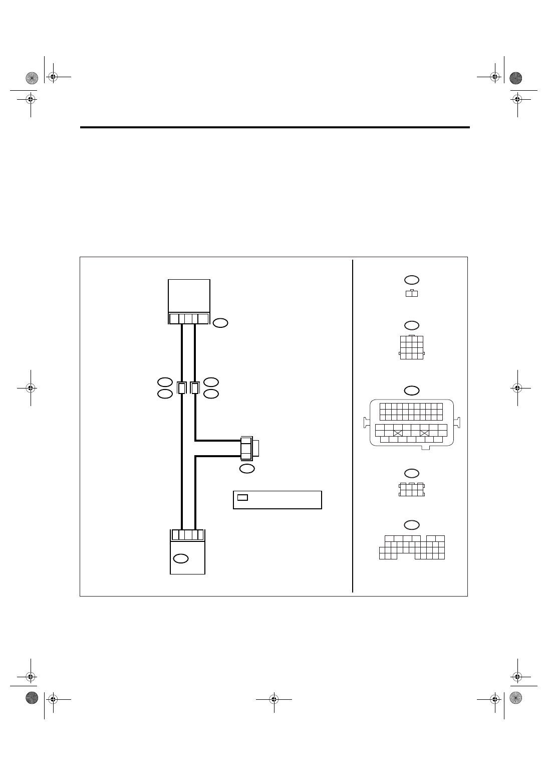
WIRING DIAGRAM:
EN-03500
E75
E2
B21
B136
ECM
B83
1
19
35
E1
B20
2
3
27
*
: TERMINAL No.
RANDOM ARRANGEMENT
*
*
E75
1 2
B20
1 2 3 4
5 6 7 8
9 10 11 12
13 14 15 16
B21
1 2 3 4
12 13 14 15
5 6 7 8
16 17 18 19
9 10 11
20 21 22
23 24 25 26 27 28 29 30 31 32 33
35
34
37
36
39
38
41
40
43
42
44
45
47
46
49
48
51
50
53
52
54
B136
5
6
7 8
2
1
9
4
3
10
24
22 23
25
11 12 13 14 15
26 27
28
16
17 18 19 20 21
33 34
29
32
30
31
35
1 2 3 4
5 6 7 8
B83
OIL
TEMPERATURE
SENSOR

EN(H6DO)(diag)-171
ENGINE (DIAGNOSTICS)
Diagnostic Procedure with Diagnostic Trouble Code (DTC)
Step
Check
Yes
No
1
CHECK HARNESS BETWEEN OIL TEMPER-
ATURE SENSOR AND ECM CONNECTOR.
1) Turn the ignition switch to OFF.
2) Disconnect the connector from oil tempera-
ture sensor.
3) Measure the voltage between oil tempera-
ture sensor connector and engine ground.
Connector & terminal
(E75) No. 2 (+) — Engine ground (
−
):
Is the voltage more than 10 V? Repair the battery
short circuit of har-
ness between
ECM and oil tem-
perature sensor
connector.
2
CHECK HARNESS BETWEEN OIL TEMPER-
ATURE SENSOR AND ECM CONNECTOR.
1) Turn the ignition switch to ON.
2) Measure the voltage between oil tempera-
ture sensor connector and engine ground.
Connector & terminal
(E75) No. 2 (+) — Engine ground (
−
):
Is the voltage more than 10 V? Repair the battery
short circuit of har-
ness between
ECM and oil tem-
perature sensor
connector.
3
CHECK HARNESS BETWEEN OIL TEMPER-
ATURE SENSOR AND ECM CONNECTOR.
Measure the voltage between oil temperature
sensor connector and engine ground.
Connector & terminal
(E75) No. 2 (+) — Engine ground (
−
):
Is the voltage more than 4 V?
Repair the har-
ness and connec-
tor.
NOTE:
In this case, repair
the following:
• Open circuit of
harness between
ECM and oil tem-
perature sensor
connector
• Poor contact in
oil temperature
sensor connector
• Poor contact in
ECM connector
• Poor contact in
coupling connector
4
CHECK HARNESS BETWEEN OIL TEMPER-
ATURE SENSOR AND ECM CONNECTOR.
1) Turn the ignition switch to OFF.
2) Measure the resistance of harness
between oil temperature sensor connector and
engine ground.
Connector & terminal
(E75) No. 1 — Engine ground:
Is the resistance less than 5
Ω?
Replace the oil
temperature sen-
sor. <Ref. to
FU(H6DO)-29, Oil
Temperature Sen-
sor.>
Repair the har-
ness and connec-
tor.
NOTE:
In this case, repair
the following:
• Open circuit of
harness between
ECM and oil tem-
perature sensor
connector
• Poor contact in
oil temperature
sensor connector
• Poor contact in
ECM connector
• Poor contact in
coupling connector
• Poor contact in
joint connector
EN(H6DO)(diag)-172
ENGINE (DIAGNOSTICS)
Diagnostic Procedure with Diagnostic Trouble Code (DTC)
AW:DTC P0222 THROTTLE/PEDAL POSITION SENSOR/SWITCH “B” CIRCUIT
LOW
DTC DETECTING CONDITION:
Immediately at fault recognition
TROUBLE SYMPTOM:
• Erroneous idling
• Poor driving performance
• Engine stalls.
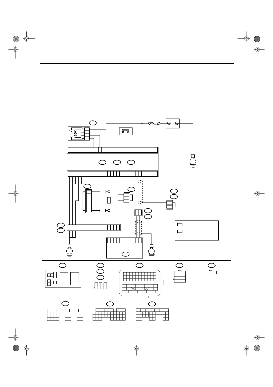
WIRING DIAGRAM:
EN-03499
SBF-7
B135
B:
B137
B136
D:
B362
E1
B20
B83
B122
C:
E
E
E
D6
B35
38
39
20
19
16
15
*
*
E2
B21
E57
4
6
1
2
3
5
D4
D5
C35
C16
B1
B4
D1
D2
D3
36
35
37
C29
C18
ECM
5
6
B362
B20
B21
E57
B122
B83
B138
1 2
7 8
3
4
5
6
1 2 3 4 5 6 7 8 9 10 11
12 13 14 15 16 17 18 19 20 21 22
23 24 25
34 35
36 37 38 39 40 41
48 49
50 51 52 53 54
42 43
44 45
46 47
26 27 28 29 30 31 32 33
1 2 3 4
5 6 7 8
1
2
7
8 9
5
6
3
4
10 11 12
19 20 21
29
30 31
13 14 15 16 17
27
28
18
22 23
24 25
26
1
2
8 9
5
6
3
4
10 11 12
19 20 21
29 30
31
13 14 15 16
17
27
28
18
22 23 24 25 26
7
32 33 34 35
B136
C:
B137
D:
BATTERY
MAIN RELAY
ELECTRONIC
THROTTLE
CONTROL RELAY
ELECTRONIC
THROTTLE CONTROL
1 2 3 4
5 6 7 8
9 10 11 12
13 14 15 16
1 2 3 4 5 6
*
*
1
*
2
*
2
1
1
1
*
1 : TERMINAL No.
RANDOM ARRANGEMENT
B135
5
6
7
8
2
1
9
4
3
10
24
22 23
25
11 12 13 14 15
26 27
28
16 17 18 19
20 21
29 30 31
32 33
34 35
B:
8
7
RHD
RHD
LHD
*
: TERMINAL No.
RANDOM ARRANGEMENT
AMONG 3,4,7, AND 8
2
B122
B138
: LHD
: RHD
Нет комментариевНе стесняйтесь поделиться с нами вашим ценным мнением.
Текст