Subaru Legacy (2005 year). Service manual — part 567
4AT(diag)-105
AUTOMATIC TRANSMISSION (DIAGNOSTICS)
Diagnostic Procedure with Diagnostic Trouble Code (DTC)
Step
Check
Yes
No
1
CHECK TCM SIGNAL.
1) Connect the Subaru Select Monitor to the
data link connector.
2) Turn the ignition switch to ON.
3) Read the data of “Throttle sensor power
supply” using Subaru Select Monitor.
Is the value less than 4.75 V?
2
CHECK HARNESS CONNECTOR BETWEEN
TCM AND ACCELERATOR PEDAL POSI-
TION SENSOR.
1) Turn the ignition switch to OFF.
2) Disconnect the connector from TCM.
3) Measure the resistance of harness
between TCM and accelerator pedal position
sensor connector.
Connector & terminal
2.5L EC, K4, EK model
(B55) No. 10 — (B315) No. 1:
Except for 2.5L EC, K4 ,EK model
(B55) No. 19 — (B315) No. 2:
Is the resistance less than 1
Repair the open
circuit of harness
between TCM and
accelerator pedal
position sensor
connector, and
poor contact of
connector.
3
CHECK HARNESS CONNECTOR BETWEEN
TCM AND ECM.
1) Disconnect the connector from ECM.
2) Measure the resistance of harness
between TCM and ECM connector.
Connector & terminal
2.0L model and 2.5L KA, KS model
(B54) No. 10 — (B137) No. 18:
2.5L EK, EC, K4 model
(B54) No. 10 — (B136) No. 16:
Is the resistance less than 1
Repair the open
circuit of harness
between TCM and
ECM connector,
and poor contact
of connector.
4
CHECK HARNESS CONNECTOR AMONG
TCM, ACCELERATOR PEDAL POSITION
SENSOR AND ECM.
Measure the resistance of harness between
TCM connector and chassis ground.
Connector & terminal
(B54) No. 10 — Chassis ground:
Is the resistance 1 M
Ω or
more?
Repair the short
circuit of harness
among TCM,
accelerator pedal
position sensor
and ECM connec-
tor.
5
CHECK HARNESS CONNECTOR BETWEEN
TCM CONNECTOR AND TRANSMISSION
GROUND.
1) Disconnect the connector from transmission.
2) Measure the resistance of harness
between TCM and transmission connector.
Connector & terminal
(B54) No. 8 — (B11) No. 19:
(B54) No. 17 — (B11) No. 19:
(B55) No. 2 — (B11) No. 20:
(B55) No. 3 — (B11) No. 20:
Is the resistance less than 1
Repair the open
circuit of harness
between TCM and
transmission con-
nector, and poor
contact of connec-
tor.
6
CHECK CIRCUIT BETWEEN TRANSMIS-
SION CONNECTOR AND TRANSMISSION
GROUND.
Measure the resistance of harness between
transmission connector and transmission case.
Connector & terminal
(B11) No. 19 — Transmission ground:
(B11) No. 20 — Transmission ground:
Is the resistance less than 1
Repair the open
circuit of harness
between transmis-
sion connector
and transmission
ground, poor con-
tact of connector
and insufficient
tightening of
ground bolt.
4AT(diag)-106
AUTOMATIC TRANSMISSION (DIAGNOSTICS)
Diagnostic Procedure with Diagnostic Trouble Code (DTC)
AA:DTC P1718 CAN COMMUNICATION CIRCUIT
NOTE:
Refer to “Body Integrated Module” for diagnosis of P1718. <Ref. to LAN(diag)-2, Basic Diagnostic Proce-
dure.>
7
CHECK ECM POWER SUPPLY AND
GROUND LINE.
Check ECM power supply circuit and ground
circuit. <Ref. to EN(H4SO 2.0)(diag)-54,
CHECK POWER SUPPLY AND GROUND
LINE OF ENGINE CONTROL MODULE
(ECM), Diagnostics for Engine Starting Fail-
ure.> <Ref. to EN(H4SO 2.5)(diag)-57,
CHECK POWER SUPPLY AND GROUND
LINE OF ENGINE CONTROL MODULE
(ECM), Diagnostics for Engine Starting Fail-
ure.> <Ref. to EN(H4DOTC)(diag)-53, CHECK
POWER SUPPLY AND GROUND LINE OF
ENGINE CONTROL MODULE (ECM), Diag-
nostics for Engine Starting Failure.> <Ref. to
EN(H6DO)(diag)-57, CHECK POWER SUP-
PLY AND GROUND LINE OF ENGINE CON-
TROL MODULE (ECM), Diagnostics for
Engine Starting Failure.>
Is there any abnormal condi-
tion?
Repair the mal-
function of ECM
power supply cir-
cuit and ground
circuit.
Replace the TCM.
<Ref. to 4AT-66,
Transmission Con-
trol Module
(TCM).>
Step
Check
Yes
No
4AT(diag)-107
AUTOMATIC TRANSMISSION (DIAGNOSTICS)
Diagnostic Procedure with Diagnostic Trouble Code (DTC)
AB:DTC P1760 LATERAL ACCELERATION SENSOR PERFORMANCE PROB-
LEM
DTC DETECTING CONDITION:
Faulty lateral G sensor output voltage
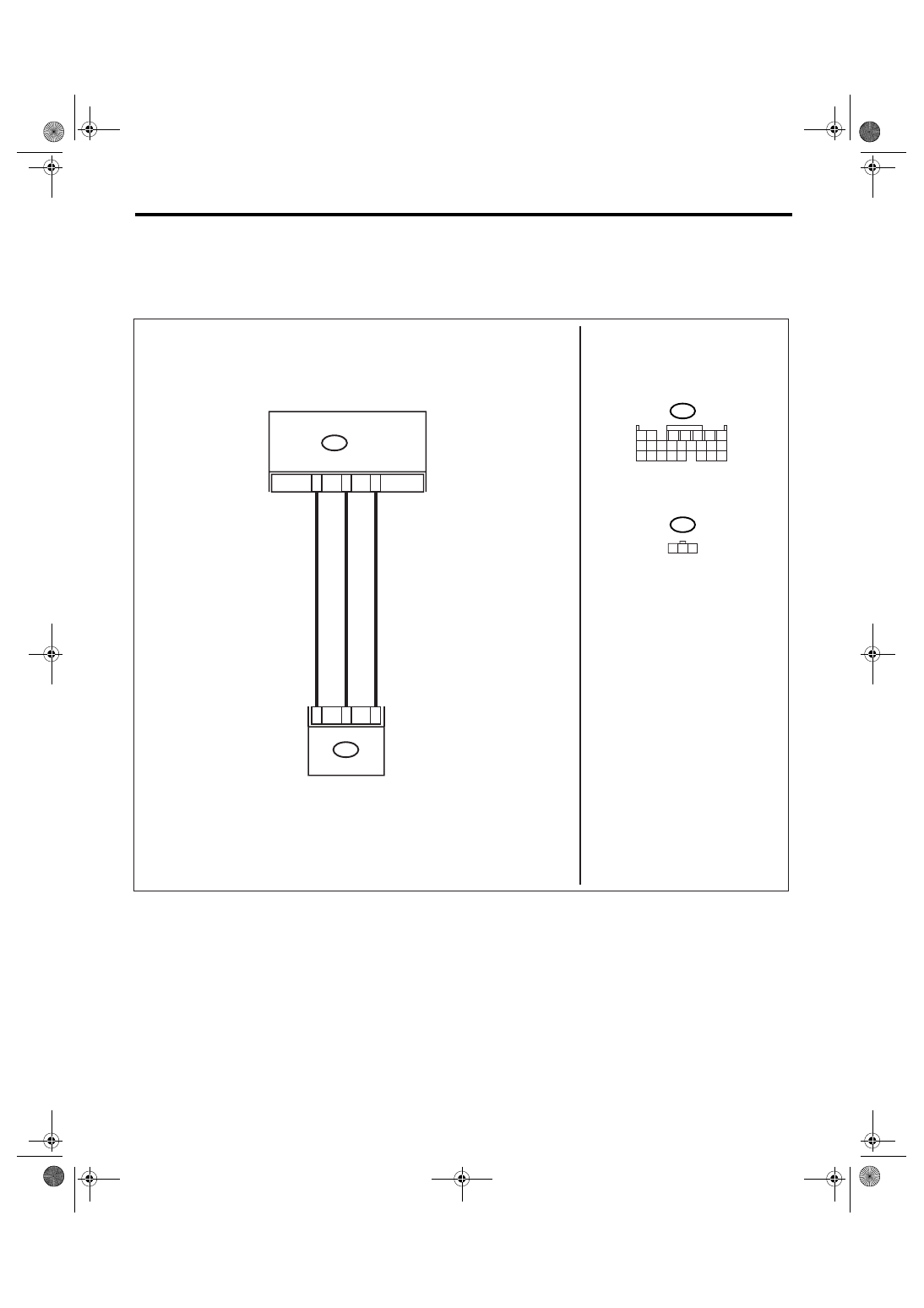
WIRING DIAGRAM:
AT-01496
11
B54
TCM
B359
1
2
3
9
2
2 3
1
B54
1 2
7
8 9
5
6
3
4
10 11 12
19 20 21
13 14 15 16
17 18
22 23 24
B359
G SENSOR
4AT(diag)-108
AUTOMATIC TRANSMISSION (DIAGNOSTICS)
Diagnostic Procedure with Diagnostic Trouble Code (DTC)
Step
Check
Yes
No
1
CHECK OUTPUT OF LATERAL G SENSOR
USING SUBARU SELECT MONITOR.
1) Select {Current Data Display & Save} in
Subaru Select Monitor.
2) Read the Subaru Select Monitor display.
Is the value on display 2.3 —
2.7 V when the vehicle is on a
level?
2
CHECK OUTPUT OF LATERAL G SENSOR
USING SUBARU SELECT MONITOR.
1) Turn the ignition switch to OFF.
2) Remove the console box.
3) Remove the lateral G sensor from vehicle.
(Do not disconnect connector.)
4) Turn the ignition switch to ON.
5) Select {Current Data Display & Save} in
Subaru Select Monitor.
6) Read the Subaru Select Monitor display.
Is the value on display 3.3 —
4.3 V when lateral G sensor is
inclined to the right to 90
°?
Replace the lat-
eral G sensor.
<Ref. to 4AT-67,
Lateral G Sensor.>
3
CHECK OUTPUT OF LATERAL G SENSOR
USING SUBARU SELECT MONITOR.
Read the Subaru Select Monitor display.
Is the value on display 0.7 —
1.7 V when lateral G sensor is
inclined to the left to 90
°?
Replace the lat-
eral G sensor.
<Ref. to 4AT-67,
Lateral G Sensor.>
4
CHECK POOR CONTACT IN CONNECTOR.
Turn the ignition switch to OFF.
Is there poor contact in con-
nector between TCM and lat-
eral G sensor?
Repair the con-
nector.
5
CHECK ABSCM&H/U.
1) Connect all the connectors.
2) Perform the clear memory mode.
3) Perform the inspection mode.
4) Read the DTC.
Is the same DTC still dis-
played?
Replace the TCM.
<Ref. to 4AT-66,
Transmission Con-
trol Module
(TCM).>
6
CHECK ANY OTHER DTC ON DISPLAY.
Is any other DTC displayed?
Perform the diag-
nosis according to
DTC.
Temporary poor
contact occurs.
7
CHECK OPEN CIRCUIT IN LATERAL G SEN-
SOR OUTPUT HARNESS AND GROUND
HARNESS.
1) Turn the ignition switch to OFF.
2) Disconnect the connector from TCM.
3) Measure the resistance between TCM con-
nector terminals.
Connector & terminal
(B54) No. 2 — No. 9:
Is the resistance 5.0 — 6.0
k
Ω?
Repair the har-
ness connector
between lateral G
sensor and TCM.
8
CHECK LATERAL G SENSOR.
1) Remove the console box.
2) Remove the lateral G sensor from vehicle.
3) Connect the connector to lateral G sensor.
4) Connect the connector to ABSCM&H/U.
5) Turn the ignition switch to ON.
6) Measure the voltage between lateral G
sensor connector terminals.
Connector & terminal
(B359) No. 3 (+) — No. 2 (
−
):
Is the voltage 2.3 — 2.7 V
when lateral G sensor is hori-
zontal?
Replace the lat-
eral G sensor.
<Ref. to 4AT-67,
Lateral G Sensor.>
9
CHECK LATERAL G SENSOR.
Measure the voltage between lateral G sensor
connector terminals.
Connector & terminal
(B359) No. 3 (+) — No. 2 (
−
):
Is the voltage 3.3 — 4.3 V
when lateral G sensor is
inclined to the right to 90
°?
Replace the lat-
eral G sensor.
<Ref. to 4AT-67,
Lateral G Sensor.>
10
CHECK LATERAL G SENSOR.
Measure the voltage between lateral G sensor
connector terminals.
Connector & terminal
(B359) No. 3 (+) — No. 2 (
−
):
Is the voltage 0.7 — 1.7 V
when lateral G sensor is
inclined to the left to 90
°?
Replace the lat-
eral G sensor.
<Ref. to 4AT-67,
Lateral G Sensor.>
Нет комментариевНе стесняйтесь поделиться с нами вашим ценным мнением.
Текст