Subaru Legacy (2005 year). Service manual — part 731
DI-31
DIFFERENTIALS
Rear Differential (T-type)
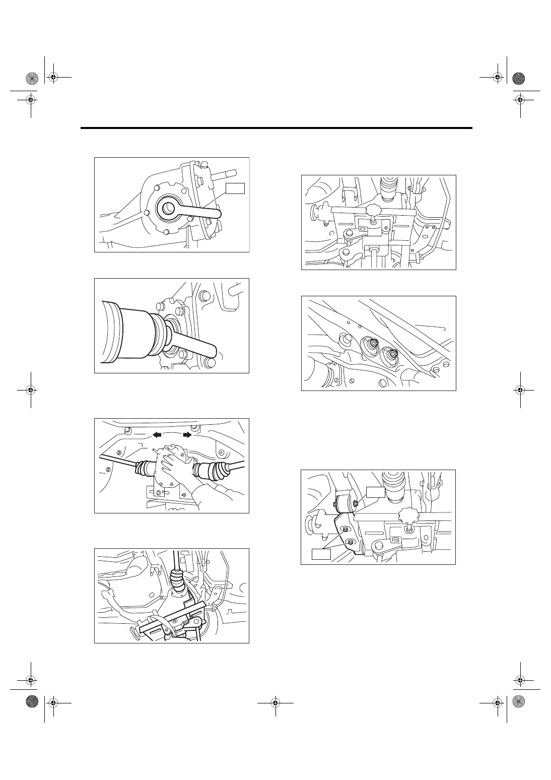
3) Install the ST to rear differential.
ST
28099PA090
OIL SEAL PROTECTOR
4) Insert the spline shaft until the spline portion
comes inside the side oil seal.
5) Remove ST from rear differential.
ST
28099PA090
OIL SEAL PROTECTOR
6) Push the rear differential to insert the axle shaft
into rear differential.
7) Adjust the transmission jack, if necessary, and
insert the rear differential stud bolt into rear cross-
member bushing properly.
8) After inserting the rear differential stud bolt into
rear crossmember bushing, lift up the transmission
jack and align the rear differential with its own posi-
tion.
9) Tighten the rear crossmember self-locking nut
temporarily.
10) Remove the band from rear differential. Lift up
the rear differential until the rear differential is sep-
arated from the transmission jack.
11) Install the rear differential front member.
Tightening torque:
T1: 52 N
⋅
m (5.3 kgf-m, 38 ft-lb)
T2: 110 N
⋅
m (11.2 kgf-m, 81 ft-lb)
DI-00279
ST
DI-00280
DI-00281
DI-00393
DI-00283
DI-00269
DI-00284
T2
T1
DI-32
DIFFERENTIALS
Rear Differential (T-type)
12) Tighten the self-locking nut.
Tightening torque:
70 N
⋅
m (7.1 kgf-m, 51 ft-lb)
13) Lower the transmission jack.
14) Install the propeller shaft. <Ref. to DS-11, IN-
STALLATION, Propeller Shaft.>
15) Install the heat shield cover.
16) Install the rear exhaust pipe and muffler.
17) After installing the rear differential carrier to the
vehicle, remove the filler plug, and refill the gear oil
to the bottom of plug hole.
Oil capacity:
0.8
2 (0.8 US qt, 0.7 Imp qt)
18) Tighten the filler plug.
NOTE:
Apply liquid gasket to the drain plug.
Liquid gasket:
THREE BOND 1105 (Part No. 004403010) or
equivalent
Tightening torque:
49 N
⋅
m (5.0 kgf-m, 36.2 ft-lb)
C: DISASSEMBLY
To detect the real cause of trouble, inspect the fol-
lowing items before disassembling.
• Tooth contact of hypoid driven gear and drive
pinion, and backlash
• Hypoid driven gear runout on its back surface
• Total preload of drive pinion
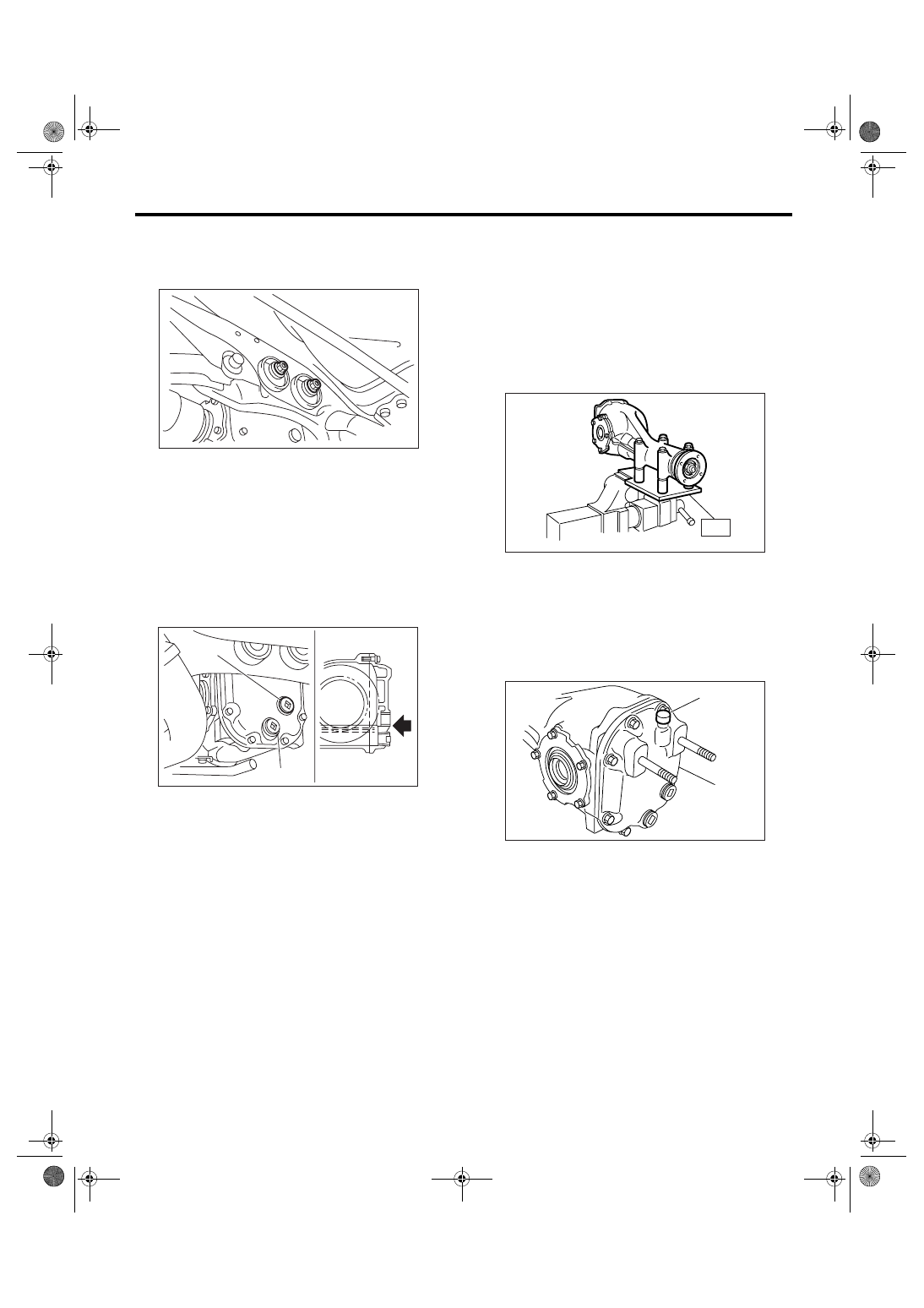
1) Set the ST on vise and install the differential as-
sembly to ST.
ST
398217700
ATTACHMENT SET
2) Drain the gear oil by removing plug.
3) Remove the air breather cap.
NOTE:
• Do not attempt to replace the air breather cap un-
less necessary.
• Replace the air breather cap with a new one
when removing it.
(A) Filler plug
(B) Drain plug
DI-00269
DI-00285
(A)
(B)
(A) Air breather cap
(B) Rear cover
ST
DI-00061
(A)
(B)
DI-00062
DI-33
DIFFERENTIALS
Rear Differential (T-type)
4) Remove the bolts, and then remove the rear
cover.
NOTE:
Remove it by tapping with plastic hammer.
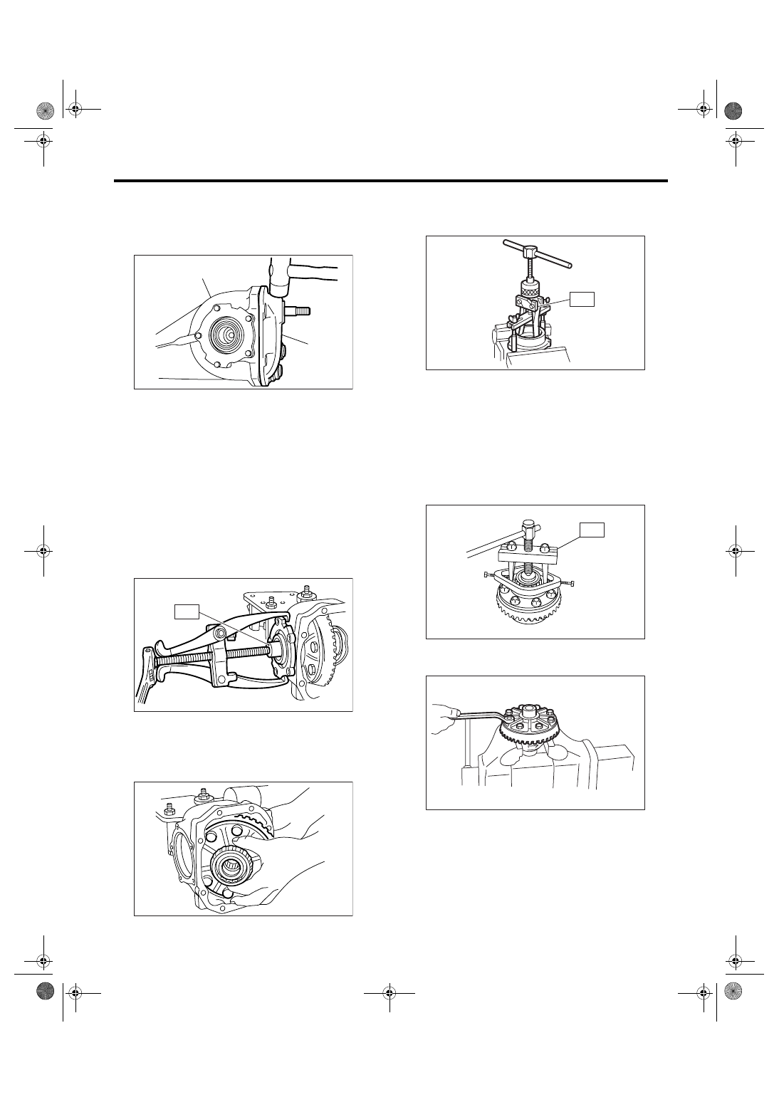
5) Keep the side bearing retainers RH and LH sep-
arately for easier reassembly. Remove the side
bearing retainer attaching bolts, set the ST to differ-
ential case, and extract the side bearing retainers
RH and LH with a puller.
NOTE:
Each shim, which is installed to adjusted the side
bearing preload, should be kept together with its
mating retainer.
ST
398457700
ATTACHMENT
6) Pull out the differential case assembly from dif-
ferential carrier.
NOTE:
Be careful not to hit the teeth against the case.
7) When replacing the side bearing, remove the
bearing cup from side bearing retainer using ST.
ST
398527700
PULLER ASSY
8) Extract the bearing cone with ST.
NOTE:
• Do not attempt to disassemble the parts unless
necessary.
• Set the puller so that its claws catch the edge of
the bearing cone.
• Never mix up the bearing races RH and LH and
cones.
ST
18759AA000
PULLER ASSY
9) Remove the hypoid driven gear by loosening hy-
poid driven gear bolts.
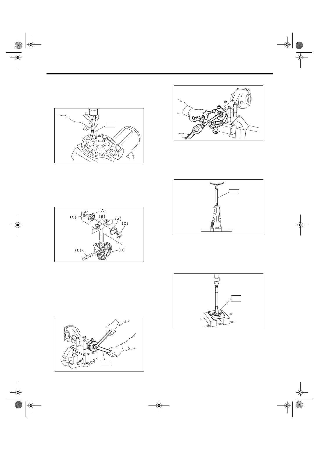
10) Drive out the pinion shaft lock pin from hypoid
driven gear side (Model without LSD).
(A) Rear cover
(B) Differential carrier
(A)
(B)
DI-00063
ST
DI-00064
DI-00065
ST
DI-00066
DI-00316
ST
DI-00068
DI-34
DIFFERENTIALS
Rear Differential (T-type)
NOTE:
The lock pin is staked at the pin hole end on the dif-
ferential carrier. Do not drive it out forcibly before
removing the stake.
ST
899904100
STRAIGHT PIN REMOVER
11) Draw out the pinion mate shaft and remove pin-
ion mate gears, side gears and thrust washers.
(Model without LSD)
NOTE:
The gears should be marked or kept separated
right and left, and front and rear as well as thrust
washers.
12) Hold the companion flange with ST and remove
the self-locking nut.
ST
498427200
FLANGE WRENCH
13) Extract the companion flange with a puller.
14) Press the end of drive pinion shaft and extract it
together with rear bearing cone, pinion height ad-
just washer and washer.
NOTE:
Hold the drive pinion so as not to drop it.
ST
398467700
DRIFT
15) Remove the rear bearing cone from drive pin-
ion by supporting the cone with ST.
NOTE:
Place the replacer so that its center-recessed side
faces the pinion gear.
ST
398517700
REPLACER
(A) Side gear
(B) Pinion mate gear
(C) Thrust washer
(D) Differential case
(E) Pinion mate shaft
DI-00237
ST
DI-00238
ST
DI-00071
DI-00072
ST
DI-00073
ST
DI-00074
Нет комментариевНе стесняйтесь поделиться с нами вашим ценным мнением.
Текст