Subaru Legacy (2005 year). Service manual — part 946
ET-17
ENTERTAINMENT
Navigation Body
16.Navigation Body
A: REMOVAL
1) Disconnect the ground cable from battery.
2) Remove the glove box. <Ref. to EI-51, REMOV-
AL, Glove Box.>
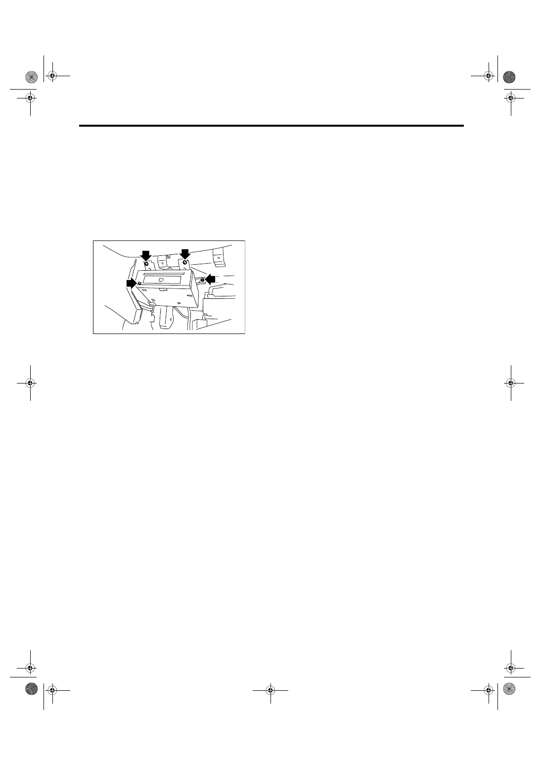
3) Remove the navigation body mounting screws in
numerical order and pull it out.
NOTE:
To remove the screw (4) easier, move the naviga-
tion body after removing the screw (3).
4) Remove the harness connector and antenna ca-
ble, and then remove the navigation body.
B: INSTALLATION
Install in the reverse order of removal.
ET-00107
(2)
(3)
(4)
(1)
ET-18
ENTERTAINMENT
Front Accessory Power Supply Socket
17.Front Accessory Power Sup-
ply Socket
A: REMOVAL
1. FRONT
1) Disconnect the ground cable from battery.
2) Remove the console front panel. <Ref. to EI-54,
REMOVAL, Center Console.>
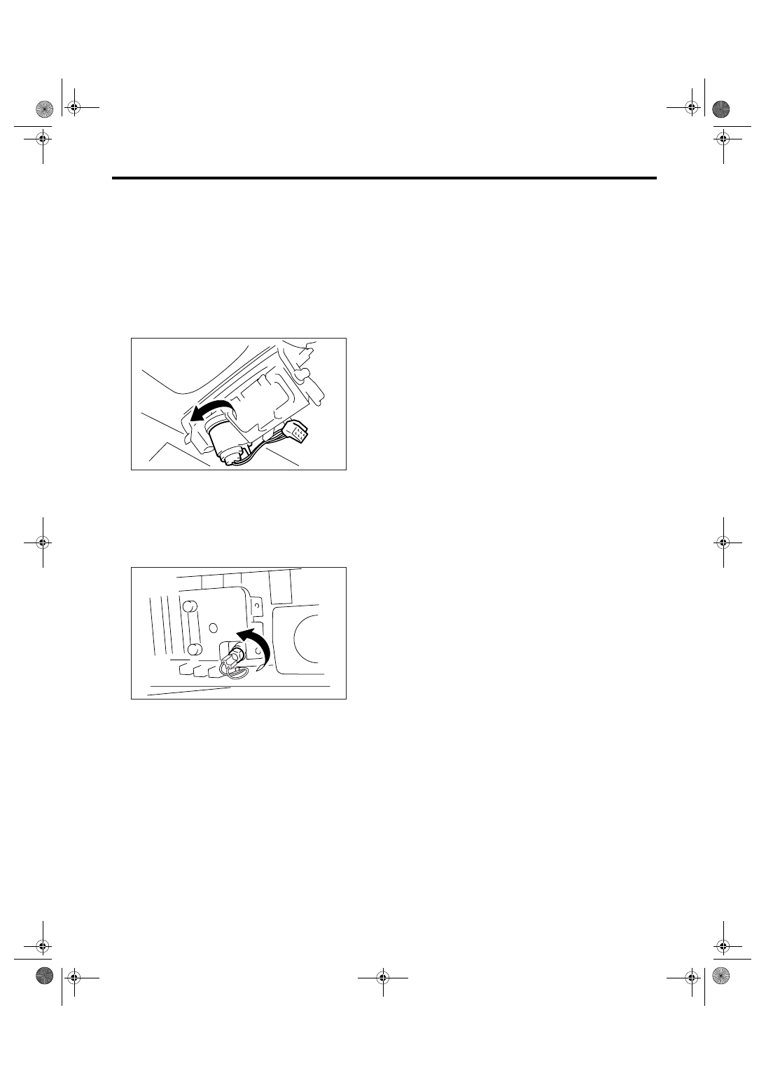
3) Disconnect the harness connector, and remove
the accessory power supply socket.
2. REAR
1) Disconnect the ground cable from battery.
2) Remove the console box. <Ref. to EI-53, RE-
MOVAL, Console Box.>
3) Disconnect the harness connector, and remove
the accessory power supply socket.
B: INSTALLATION
Install in the reverse order of removal.
ET-00094
ET-00095
ET-19
ENTERTAINMENT
Steering Satellite Switch
18.Steering Satellite Switch
A: REMOVAL
1) Disconnect the ground cable from battery.
2) Set the tire to the straight-ahead position.
3) Remove the airbag module. <Ref. to AB-16, RE-
MOVAL, Driver’s Airbag Module.>
WARNING:
With the airbag module equipped, always refer
to “Airbag System” when performing the airbag
module repair service. <Ref. to AB-16, INSPEC-
TION, Driver’s Airbag Module.>
4) Remove the steering wheel. <Ref. to PS-21, RE-
MOVAL, Steering Wheel.>
5) Remove the cover from steering wheel.
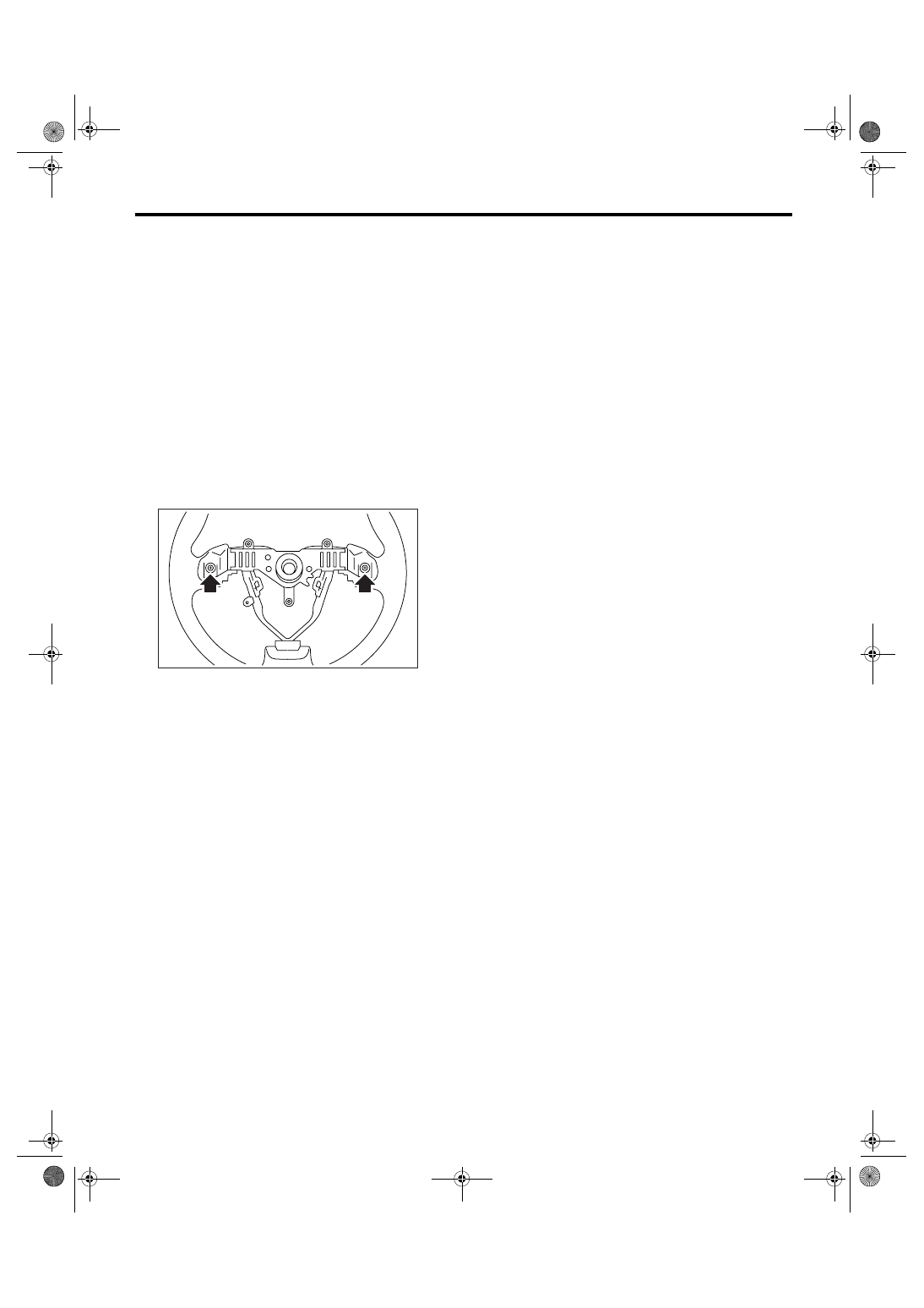
6) Remove each one of satellite switch mounting
screw from the LH and RH side.
7) Remove the satellite switch.
B: INSTALLATION
Install in the reverse order of removal.
CS-00331
ET-20
ENTERTAINMENT
Steering Satellite Switch
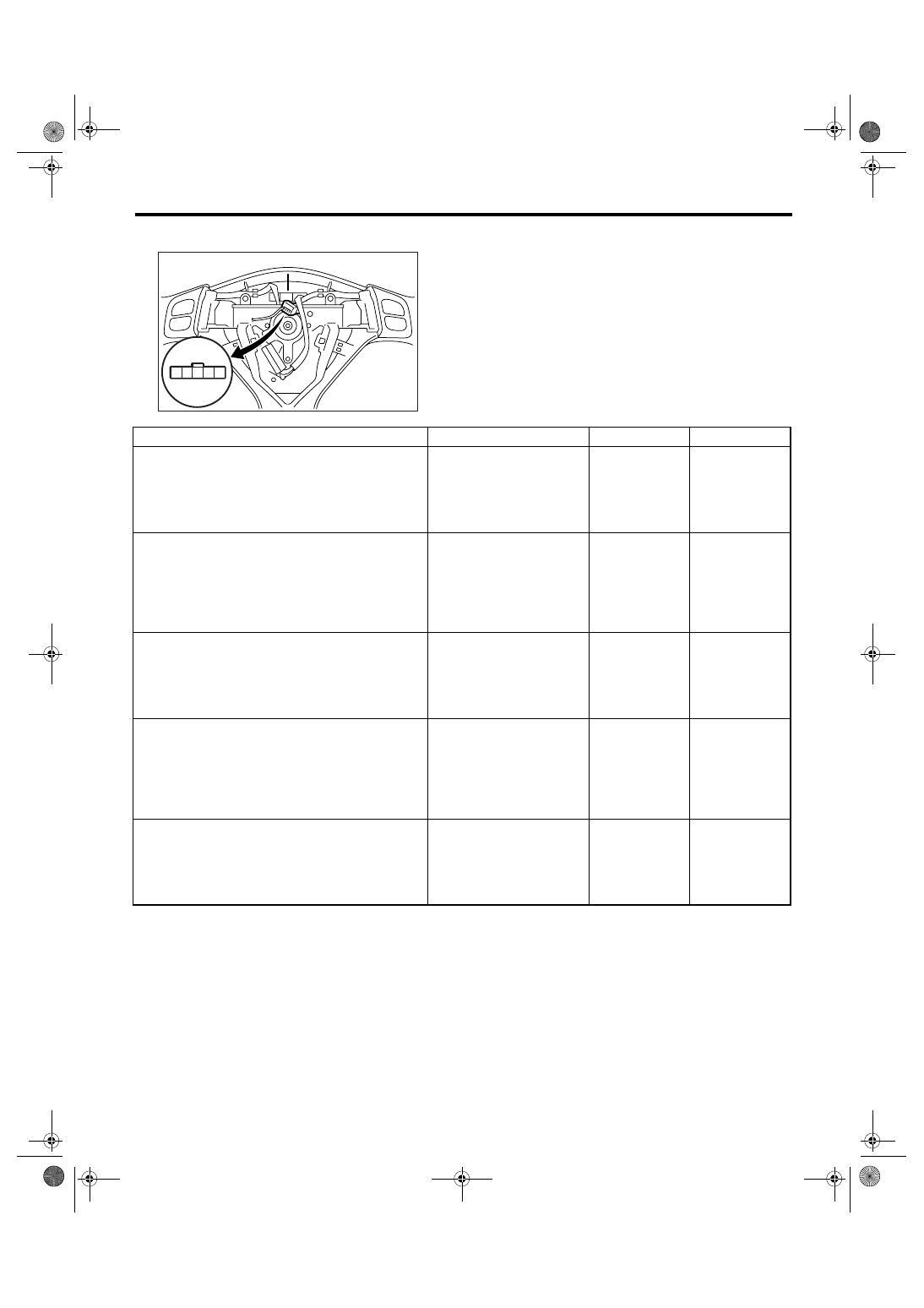
C: INSPECTION
CS-00387
1
5
2 3 4
Step
Check
Yes
No
1
MUTE SWITCH CONTINUITY CHECK.
1) Press the mute switch.
2) Measure the resistance between satellite
switch connector terminals.
Terminals
No. 1 — No. 2:
Is the resistance approx. 22
Replace the satel-
lite switch.
2
VOLUME SWITCH CONTINUITY CHECK.
1) Press the volume switch.
2) Measure the resistance between satellite
switch connector terminals.
Terminals
No. 1 — No. 2: Volume up
No. 1 — No. 2: Volume down
Is the resistance approx. 90
Ω?
(Volume up) Is the resistance
approx. 200
Ω? (Volume down)
Replace the satel-
lite switch.
3
MODE SWITCH CONTINUITY CHECK.
1) Press the mode switch.
2) Measure the resistance between satellite
switch connector terminals.
Terminals
No. 1 — No. 2:
Is the resistance approx. 360
Ω?
Replace the satel-
lite switch.
4
SEEK SWITCH CONTINUITY CHECK.
1) Press the seek switch.
2) Measure the resistance between satellite
switch connector terminals.
Terminals
No. 1 — No. 2: Seek up
No. 1 — No. 2: Seek down
Is the resistance approx. 690
Ω? (Seek up) Is the resistance
approx. 1.5 k
Ω? (Seek down)
Replace the satel-
lite switch.
5
CHECK SATELLITE SWITCH INSULATION.
1) Not to operate the satellite switch.
2) Measure the resistance between satellite
switch connector terminals.
Terminals
No. 1 — No. 2:
Is the resistance approx. 4.7
k
Ω?
Satellite switch is
normal.
Replace the satel-
lite switch.
Нет комментариевНе стесняйтесь поделиться с нами вашим ценным мнением.
Текст