Subaru Legacy (2005 year). Service manual — part 107
EN(H4SO 2.0)(diag)-17
ENGINE (DIAGNOSTICS)
Engine Control Module (ECM) I/O Signal
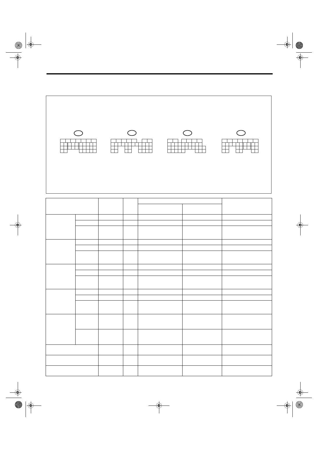
5. Engine Control Module (ECM) I/O Signal
A: ELECTRICAL SPECIFICATION
DESCRIPTION
Connector
No.
Termi-
nal
No.
Signal (V)
NOTE
Ignition SW ON
(engine OFF)
Engine ON
(idling)
Crankshaft
position sen-
sor (Model
with immobi-
lizer)
Signal (+)
B136
27
0
−7 — +7
Sensor output waveform
Signal (
−)
B136
24
0
0
—
Shield
B136
32
0
0
—
Crankshaft
position sen-
sor (Model
without immo-
bilizer)
Signal (+)
B136
26
0
−7 — +7
Sensor output waveform
Signal (
−)
B136
24
0
0
—
Shield
B136
32
0
0
—
Camshaft
position sen-
sor (Model
with immobi-
lizer)
Signal (+)
B136
26
0
−7 — +7
Sensor output waveform
Signal (
−)
B136
25
0
0
—
Shield
B136
32
0
0
—
Camshaft
position sen-
sor (Model
without immo-
bilizer)
Signal (+)
B136
27
0
−7 — +7
Sensor output waveform
Signal (
−)
B136
25
0
0
—
Shield
B136
32
0
0
—
Electronic
throttle control
Main
B137
23
0.4 — 1.1
Fully opened:
3.7 — 4.3
0.3 — 0.9
(After engine is
warmed-up.)
—
Sub
B137
24
3.9 — 4.8
Fully opened:
0.65 — 1.5
4.05 — 4.95
(After engine is
warmed-up.)
—
Electronic throttle control
motor 1 (+)
B137
2
Duty waveform
Duty waveform
Drive frequency: 1 kHz
Electronic throttle control
motor 2 (+)
B137
3
Duty waveform
Duty waveform
Drive frequency: 1 kHz
Electronic throttle control
motor 1 (
−)
B137
4
Duty waveform
Duty waveform
Drive frequency: 1 kHz
EN-01812
B134
5
6
7
8
2
1
9
4
3
10
24
22
23
25
11
12
13
14
15
26
27
28
16
17
18
19
20
21
33
34
29
32
30
31
B136
5
6
7
8
2
1
9
4
3
10
24
22
23
25
11
12
13
14
15
26
27
28
16
17
18
19
20
21
33
34
29
32
30
31
35
B135
5
6
7
8
2
1
9
4
3
10
24
22
23
25
11
12
13
14
15
26
27
28
16
17
18
19
20
21
29
30
31
32
33
34
35
B137
5
6
7
8
2
1
9
4
3
10
22
23
11
12
13
14
15
24
25
26
16
17
18
19
20
21
27
28
29
30
31
To
To
To
To
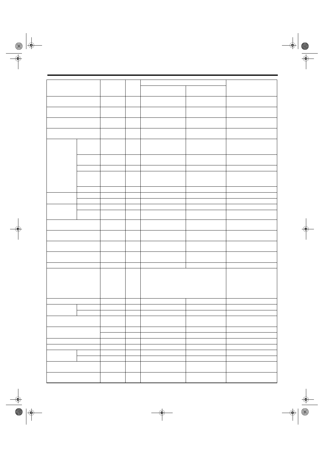
EN(H4SO 2.0)(diag)-18
ENGINE (DIAGNOSTICS)
Engine Control Module (ECM) I/O Signal
Electronic throttle control
motor 2 (
−)
B137
5
Duty waveform
Duty waveform
Drive frequency: 1 kHz
Electronic throttle control
motor 1 power supply
B137
6
10 — 13
13 — 14
—
Electronic throttle control
motor 2 power supply
B137
7
10 — 13
13 — 14
—
Electronic throttle control
motor relay
B137
9
ON: 0
OFF: 10 — 13
ON: 0
OFF: 13 — 14
When ignition switch is
turned to ON: ON
Accelerator
pedal position
sensor
Main
B137
29
Fully closed: 0.5 — 1.5
Fully opened: 3 — 5
Fully closed:
0.5 — 1.5
Fully opened: 3 — 5
—
Power
supply
B137
25
5
5
—
Ground
B137
31
0
0
—
Sub
B137
30
Fully closed: 0.5 — 1.5
Fully opened: 3 — 5
Fully closed:
0.5 — 1.5
Fully opened: 3 — 5
—
Shield
B137
19
0
0
—
Rear oxygen
sensor
Signal
B136
19
0
0 — 0.9
—
Shield
B136
30
0
0
—
Front oxygen
(A/F) sensor
heater
Signal 1
B135
2
0 — 1.0
13 — 14
—
Signal 2
B135
3
0 — 1.0
13 — 14
—
Rear oxygen sensor heater
signal
B134
1
0 — 1.0
13 — 14
—
Engine coolant temperature
sensor
B136
22
1.0 — 1.6
1.0 — 1.6
After engine is warmed-up.
Starter switch
B135
23
OFF: 0
ON: 10 — 13
OFF: 0
ON: 13 — 14
—
A/C switch
B135
20
ON: 10 — 13
OFF: 0
ON: 13 — 14
OFF: 0
—
Ignition switch
B135
13
10 — 13
13 — 14
—
Neutral position switch
B135
12
ON: 0
OFF: 10 — 14
• For AT model switch is
ON when shifted into “P”
or “N” range.
• For MT model switch is
ON when shifted into “N”
range.
Test mode connector
B135
24
5
5
When connected: 0
Knock sensor
Signal
B136
23
2.8
2.8
—
Shield
B136
12
0
0
—
Backup power supply
B136
7
10 — 13
13 — 14
Ignition switch “OFF”: 10
— 13
Control module power sup-
ply
B136
3
10 — 13
13 — 14
—
B136
4
10 — 13
13 — 14
—
Sensor power supply 1
B136
17
5
5
—
Sensor power supply 2
B137
25
5
5
—
Ignition control
1
B134
23
0
1 — 3.4
Waveform
2
B134
24
0
1 — 3.4
Waveform
Blower fan switch
B135
11
ON: 0
OFF: 10 — 13
ON: 0
OFF: 13 — 14
—
A/C middle pressure switch
B135
8
ON: 0
OFF: 10 — 13
ON: 0
OFF: 13 — 14
—
DESCRIPTION
Connector
No.
Termi-
nal
No.
Signal (V)
NOTE
Ignition SW ON
(engine OFF)
Engine ON
(idling)
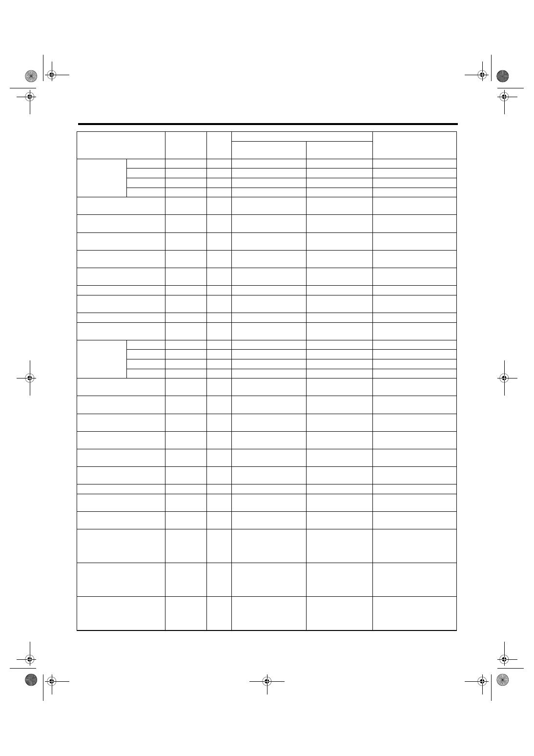
EN(H4SO 2.0)(diag)-19
ENGINE (DIAGNOSTICS)
Engine Control Module (ECM) I/O Signal
Fuel injector
#1
B134
17
10 — 13
1 — 14
Waveform
#2
B134
27
10 — 13
1 — 14
Waveform
#3
B134
34
10 — 13
1 — 14
Waveform
#4
B134
33
10 — 13
1 — 14
Waveform
Fuel pump relay control
(Model with immobilizer)
B135
17
0.5 or less
0.5 or less
—
Fuel pump relay control
(Model without immobilizer)
B134
18
0.5 or less
0.5 or less
—
A/C relay control
B135
35
ON: 0.5 or less
OFF: 10 — 13
ON: 0.5 or less
OFF: 13 — 14
—
Radiator fan relay 1 control
B134
10
ON: 0.5 or less
OFF: 10 — 13
ON: 0.5 or less
OFF: 13 — 14
—
Radiator fan relay 2 control
B134
9
ON: 0.5 or less
OFF: 10 — 13
ON: 0.5 or less
OFF: 13 — 14
—
Self-shutoff control
B135
14
10 — 13
13 — 14
—
Malfunction indicator light
B135
15
1 or less
—
Light ON: 1 or less
Light OFF: 10 — 14
Engine speed output
B135
27
—
0 — 13 or more
Waveform
Purge control solenoid valve
B134
8
ON: 1 or less
OFF: 10 — 13
ON: 1 or less
OFF: 13 — 14
—
EGR solenoid
valve
Signal A+
B134
13
0 or 10 — 13
0 or 13 — 14
—
Signal A
−
B134
12
0 or 10 — 13
0 or 13 — 14
—
Signal B+
B134
3
0 or 10 — 13
0 or 13 — 14
—
Signal B
−
B134
4
0 or 10 — 13
0 or 13 — 14
—
Power steering switch
B135
8
ON: 1 or less
OFF: 10 — 13
ON: 1 or less
OFF: 13 — 14
—
Front oxygen (A/F) sensor
signal 1
B136
35
—
2.05 — 2.25
—
Front oxygen (A/F) sensor
signal 2
B136
33
—
2.05 — 2.25
—
Front oxygen (A/F) sensor
shield
B136
34
0
0
—
Manifold absolute pressure
sensor
B136
20
4.0 — 4.8
1.1 — 1.9
—
Intake air temperature sen-
sor
B136
28
3.3 — 3.5
3.3 — 3.5
Intake air temperature:
25
°C (75°F)
Generator control
B135
16
0 — 6.5
0 — 6.5
—
SSM communication line
B135
32
1 or less
←→ 4 or more
1 or less
←→ 4 or
more
—
Cruise control main switch
B137
14
ON: 0
OFF: 10 — 13
ON: 0
OFF: 13 — 14
—
Cruise control clutch switch
B137
22
When clutch pedal is
depressed: 0
When clutch pedal is
released: 10 — 13
When clutch pedal is
depressed: 0
When clutch pedal is
released: 13 — 14
—
Brake switch 1
B137
12
When brake pedal is
depressed: 0
When brake pedal is
released: 10 — 13
When brake pedal is
depressed: 0
When brake pedal is
released: 13 — 14
—
Brake switch 2
B137
13
When brake pedal is
depressed: 10 — 13
When brake pedal is
released: 0
When brake pedal is
depressed: 13 — 14
When brake pedal is
released: 0
—
DESCRIPTION
Connector
No.
Termi-
nal
No.
Signal (V)
NOTE
Ignition SW ON
(engine OFF)
Engine ON
(idling)
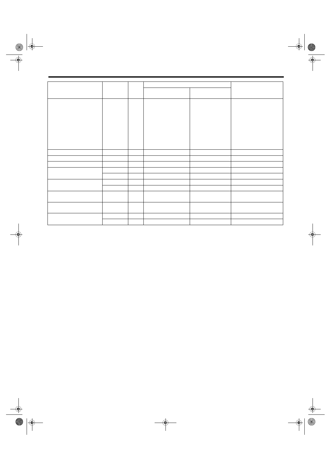
EN(H4SO 2.0)(diag)-20
ENGINE (DIAGNOSTICS)
Engine Control Module (ECM) I/O Signal
Cruise control command
switch
B136
21
When operating noth-
ing: 3.5 — 4.5
When operating RES/
ACC: 2.5 — 3.5
When operating SET/
COAST: 0.5 — 1.5
When operating CAN-
CEL: 0 — 0.5
When operating
nothing: 3.5 — 4.5
When operating
RES/ACC:
2.5 — 3.5
When operating
SET/COAST:
0.5 — 1.5
When operating
CANCEL: 0 — 0.5
—
GND (sensor 1)
B136
18
0
0
—
GND (sensor 2)
B137
31
0
0
—
GND (injector)
B134
7
0
0
—
GND (power supply)
B134
2
0
0
—
B137
1
0
0
—
GND (control system)
B136
5
0
0
—
B136
6
0
0
—
GND (oxygen sensor heater
1)
B135
5
0
0
—
GND (oxygen sensor heater
2)
B135
6
0
0
—
GND (electronic throttle
control)
B136
1
0
0
—
B136
2
0
0
—
DESCRIPTION
Connector
No.
Termi-
nal
No.
Signal (V)
NOTE
Ignition SW ON
(engine OFF)
Engine ON
(idling)
Нет комментариевНе стесняйтесь поделиться с нами вашим ценным мнением.
Текст