Subaru Legacy (2005 year). Service manual — part 1034
LAN(diag)-15
LAN SYSTEM (DIAGNOSTICS)
Subaru Select Monitor
2. READ CURRENT DATA
1) On the “Main Menu” display screen, select the {Each System Check} and press the [YES] key.
2) On the “System Selection Menu” display screen, select the {Integ. unit mode} and press the [YES] key.
3) On the “Integ. unit mode failure diag” display screen, select the {Current Data Display & Save} and press
the [YES] key.
4) On the “Current Data Display & Save” display screen, select the {12 Data Display} and press the [YES]
key.
5) Using the scroll key, scroll the display screen up or down until the desired data is shown.
• A support list contains both of analog and digital data, and they are shown in the following table.
3. DISPLAY OF ANALOG DATA
Items to be displayed
Unit of measure
NOTE
BATT Voltage (Control)
10 — 15 V
—
BATT Voltage (BACK UP)
10 — 15 V
—
IG power supply voltage
10 — 15 V
—
ACC voltage
10 — 15 V
—
Illumination VR voltage
0 — 5 V
—
Illumi. output d-ratio
0 — 100%
—
ambient temp sensor V
0 — 5 V
—
Ambient temperature
−40 — 87.5°C
—
Fuel level voltage
0 — 8 V
—
Fuel level resistance
0 — 102.3
Ω
CAN communication input value
key-lock solenoid V
6 — 12 V
—
number of regist.
0 — 4
—
Front Wheel Speed
km/h
—
VDC/ABS latest f-code
DTC display
It is normal when DTC is not been input
even if this code is displayed.
Blower fan levels
0 — 2 levels
0: OFF, 1: Low, 2: 2 levels or more
Fuel level resistance2
0 — 102.3
Ω
Output value for OBD diagnosis
Fuel consumption
cc/s
—
Coolant Temp.
−40 — 130°C
—
Vehicle lateral G
m/s
2
—
SPORT Shift Stages
0 — 7 levels
(0: light OFF, 6: fail, 7: ATF temperature
High/Low)
Shift Position
0 — 7 levels
(8 is no input)
Off delay time
OFF, Short, Normal, Long
—
Auto lock time
20, 30, 40, 50, 60 seconds
—
LAN(diag)-16
LAN SYSTEM (DIAGNOSTICS)
Subaru Select Monitor
4. DISPLAY OF ON/OFF DATA
Items to be displayed
Unit of measure
key-lock warning SW
ON/OFF
Stop Light Switch
ON/OFF
Front fog lamp SW input
ON/OFF
Rear fog lamp SW input
ON/OFF
lighting SW input
ON/OFF
Door key-lock SW input
ON/OFF
Door unlock SW input
ON/OFF
Driver’s door SW input
ON/OFF
P-door SW input
ON/OFF
Rear right door SW input
ON/OFF
Rear left door SW input
ON/OFF
R Gate SW input
ON/OFF
Manual lock SW input
ON/OFF
Manual unlock SW input
ON/OFF
Lock SW (front hood)
ON/OFF
Bright SW input
ON/OFF
Tiptronic Mode Switch
ON/OFF
TIP UPSW input
ON/OFF
TIP DOWN SW input
ON/OFF
P SW
ON/OFF
R wiper ON SW input
ON/OFF
R wiper INT SW input
ON/OFF
R washer SW input
ON/OFF
wiper deicer SW input
ON/OFF
Rear Defogger SW
ON/OFF
Driver’s Seat SW input
ON/OFF
P seatbelt SW input
ON/OFF
Fr wiper input
ON/OFF
Registration SW input
ON/OFF
Identification SW input
ON/OFF
Rr defogger output
ON/OFF
lock actuat. LOCK output
ON/OFF
All seat UNLOCK output
ON/OFF
D-seat UNLOCK output
ON/OFF
R gate/trunk UNLK output
ON/OFF
Double lock output
ON/OFF
R wiper output
ON/OFF
Shift Lock Solenoid
ON/OFF
Key locking output
ON/OFF
wiper deicer SW input
ON/OFF
Starter cutting output
ON/OFF
Hazard Output
ON/OFF
Keyless Buzzer Output
ON/OFF
Horn Output
ON/OFF
Siren Output
ON/OFF
D-belt warning light O/P
ON/OFF
P-belt warning light O/P
ON/OFF
Illumination lamp O/P
ON/OFF
Room lamp output
ON/OFF
key illumi. lamp o/p
ON/OFF
R fog lamp output
ON/OFF
R fog lamp monitor
ON/OFF
Immobilizer lamp output
ON/OFF
Keyless operation 1
Registration/Normal
Keyless operation 2
Clear/Normal
CC Main Lamp
On/Off
CC Set Lamp
On/Off
SPORT Lamp
On/Off
SPORT Blink
Blink/Off
ATF Temperature Lamp
On/Off
ATF Blink
Blink/Off
Tire diameter abnormal 1
On/Off
Tire diameter abnormal 2
Blink/Off
SPORT Shift (UP)
UP/OFF
SPORT Shift (DOWN)
DOWN/OFF
SPORT Shift (buzzer 1)
ON/OFF
SPORT Shift (buzzer 2)
ON/OFF
ABS/VDC Judging
ABS/VDC
ADA Existence Judging
Yes/No
Small light SW
ON/OFF
Headlight
ON/OFF
Headlight HI
ON/OFF
Turn signal LH
ON/OFF
Turn signal RH
ON/OFF
Rr Defogger SW
ON/OFF
Australia Judging Flag
Australia/Others
Tire 18inch flag
18 in/others
Number of cylinders
4 cylinders/6 cylinders
Cam shaft specification
SOHC/DOHC
Turbo
Turbo/Non-turbo
E/G displacement (2.5L)
2.5 L/ OFF
E/G displacement (3.0L)
3.0 L/ OFF
AT Vehicle ID Signal
AT model/MT model
E/G cooling fan
ON/OFF
Heater cock valve output
ON/OFF
Power window (Up)
ON/OFF
Power window (Down)
ON/OFF
Keyless buzzer
ON/OFF
Bright Request
ON/OFF
P/W ECM Failure
NG/OK
Keyless Hook SW
ON/OFF
Door lock SW (Open)
ON/OFF
Door lock SW (Close)
ON/OFF
Door Key SW (Open)
ON/OFF
Door Key SW (Close)
ON/OFF
Under hook registration
ON/OFF
Hook registration end
ON/OFF
Unlock request
ON/OFF
Center display failure
OK/NG
NAVI Failure
OK/NG
Items to be displayed
Unit of measure
LAN(diag)-17
LAN SYSTEM (DIAGNOSTICS)
Subaru Select Monitor
NOTE:
For details concerning operation procedure, refer
to the SUBARU SELECT MONITOR OPERATION
MANUAL.
5. CONFIRMATION OF CURRENT SETTING
1) On the “Main Menu” display screen, select the {Each System Check} and press the [YES] key.
2) On the “System Selection Menu” display screen, select the {Integ. unit mode} and press the [YES] key.
3) On the “Integ. unit mode failure diag” display screen, select the {Current Data Display & Save} and press
the [YES] key.
4) On the “Current Data Display & Save” display screen, select the {12 Data Display} and press the [YES]
key.
5) Using the scroll key, scroll the display screen up or down until the desired data is shown.
6) Display the following items and record the settings.
Required items for new registration (Except for system not equipped)
IE Bus failure
Can not use
Auto A/C failure
OK/NG
EBD Warning Light
OK/OFF
ABS Warning Light
OK/OFF
VDC OFF flag
ON/OFF
VDC/ABS OK B
OK/NG
VDC/ABS condition
0 — 4
Destinat.
0 — 16
Touch SW
0 — 64
Items to be displayed
Unit of measure
Item
Item to confirm
Remarks
Key No. to register
1
2
3
4
Registered ID type
Off delay
OFF
Long
Normal
Short
Setting for lighting off time
Auto-lock
60, 50, 40, 30, 20
OFF
(Unit sec.)
Rr defogger op. mode
Normal
Continuous
Wiper deicer op. mode
Normal
Continuous
Optional setting
Security Alarm Setup
ON
OFF
Impact Sensor Setup
ON
OFF
Optional setting
Alarm monitor delay setting
ON
OFF
Lockout prevention
ON
OFF
Impact sensor
Yes
No
Optional setting
Siren setting
Yes
No
Optional setting
Answer-back buzzer setup
ON
OFF
Not equipped
Hazard answer-back setup
ON
OFF
Automatic locking setup
ON
OFF
Ans.-back Buzzer
Yes
No
Not equipped
Auto locking
Yes
No
Door open warning (prevention of battery
run-out)
Yes
No
A/C ECM setting
Yes
No
Model with auto A/C
P/W ECM setting
Yes
No
Not equipped
Center display failure
Yes
No
Model with center display
Wiper deicer
Yes
No
Optional setting
Rear fog light setting
Yes
No
Optional setting
Factory initial setting
Factory
Market
Not change to Factory mode
Security setting (Specified security set-
ting)
Yes
No
Operate the selected security set.
(EK model)
LAN(diag)-18
LAN SYSTEM (DIAGNOSTICS)
Subaru Select Monitor
6. REGISTRATION BODY INTEGRATED
MODULE (EQUIPMENT SETTING)
CAUTION:
Body integrated module is core of LAN system,
and also can select the function of all vehicle
system control. It is possible to control the
original functions of vehicle when registrations
of body integrated module and function setting
are corresponded to vehicle equipment.
If registrations and function setting are differ-
ent from vehicle equipment, vehicle system
does not operate normally and diagnosis can-
not be performed correctly. Pay attention to
items below.
• Be sure to correspond registrations and
function settings to vehicle equipment.
• Do not change the settings of vehicle improp-
erly.
• Confirm key illumination does not blink or
“Factory initial setting” of body integrated
module registrations is “Market”. If “Factory
initial setting” is set to “Factory”, key illumina-
tion blinks with ignition key turned to ON to
give warning of unconfirmed settings.
• Key illumination does not blink with ignition
switch turned to ON and go off with door
closed.
• Be sure to register immobilizer if body inte-
grated module is replaced with a new one.
(Model with immobilizer)
• Make a registration of immobilizer when the
parts related to immobilizer have been re-
placed. Refer to “IMMOBILIZER TEACHING OP-
ERATION MANUAL”.
1) Turn the ignition switch to OFF.
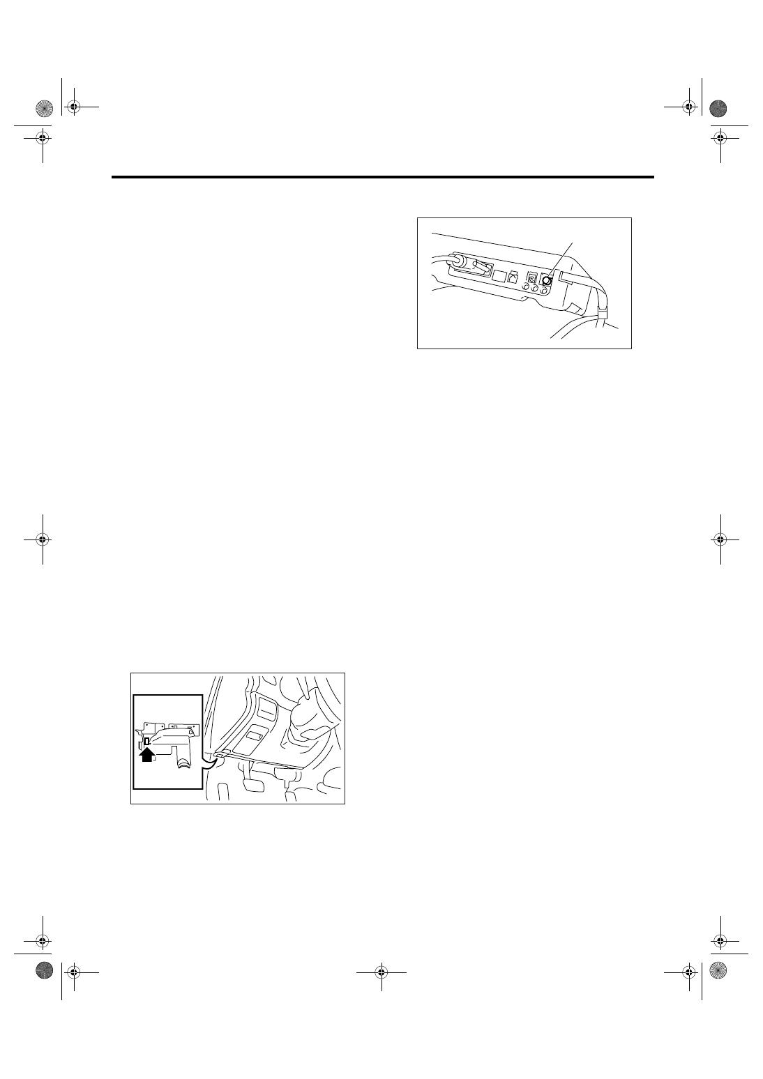
2) Connect the Subaru Select Monitor to data link
connector.
3) Turn the ignition switch to ON and the Subaru
Select Monitor power switch to ON.
4) On the “Main Menu” display screen, select the
{Each System Check} and press the [YES] key.
5) On the “Each System Check” display screen, se-
lect the {Integ. unit mode} and then select the “ECM
customizing”.
LAN00110
(A) Power switch
LAN00017
(A)
Нет комментариевНе стесняйтесь поделиться с нами вашим ценным мнением.
Текст