Subaru Legacy (2005 year). Service manual — part 1032
LAN(diag)-7
LAN SYSTEM (DIAGNOSTICS)
Electrical Component Location
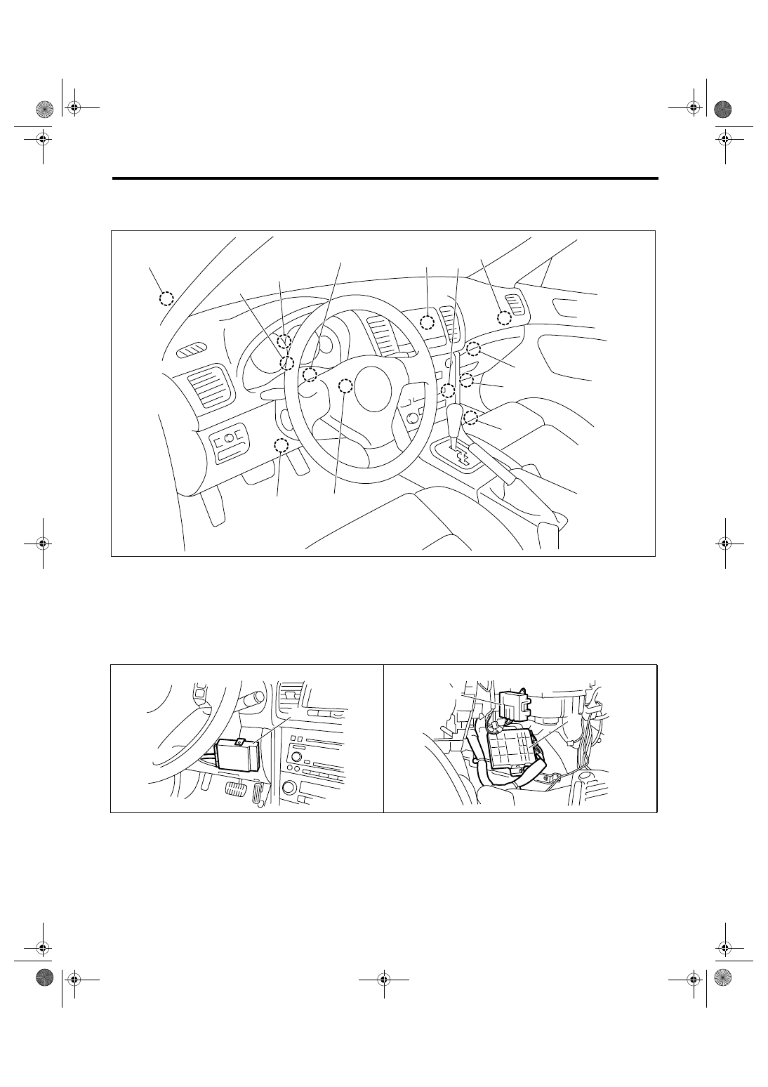
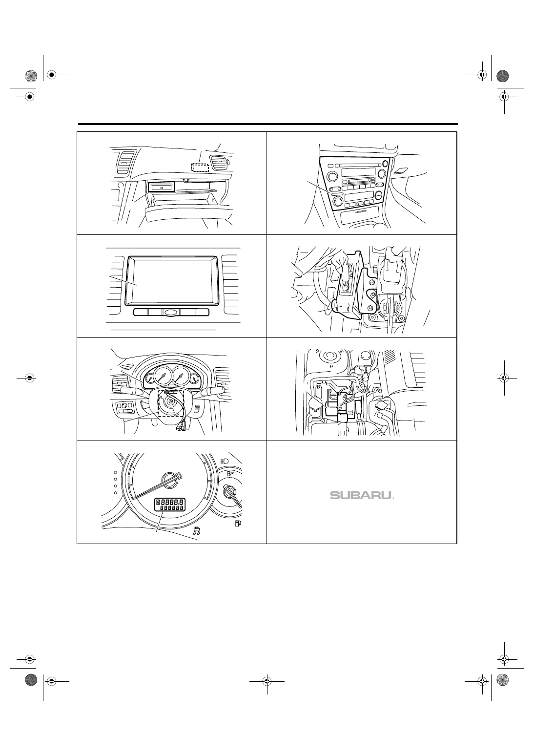
4. Electrical Component Location
A: LOCATION
(1)
Body integrated module
(6)
A/C control panel
(11)
ABSCM&H/U or VDCCM&H/U (in
engine compartment)
(2)
Engine control module (ECM)
(7)
Center display
(3)
Auto A/C control module
(8)
Transmission control module
(TCM)
(12)
Odo/trip meter
(4)
Navigation module
(5)
Keyless entry control module
(Antenna)
(9)
Combination meter
(10)
Steering angle sensor
LAN00101
(1)
(2)
(3)
(4)
(5)
(6)
(7)
(8)
(9)
(10)
(11)
(12)
LAN00102
(1)
LAN00103
(2)
(3)
LAN(diag)-8
LAN SYSTEM (DIAGNOSTICS)
Electrical Component Location
LAN00104
(4)
(5)
LAN00105
(6)
LAN00007
(7)
LAN00106
(8)
LAN00107
(9)
(10)
LAN00008
(11)
0
LAN00111
km/h
160
180
140
40
60
8
20
P
F
E
R
N
D
SPORT
CRUISE
SET
(12)
LAN(diag)-9
LAN SYSTEM (DIAGNOSTICS)
Control Module I/O Signal
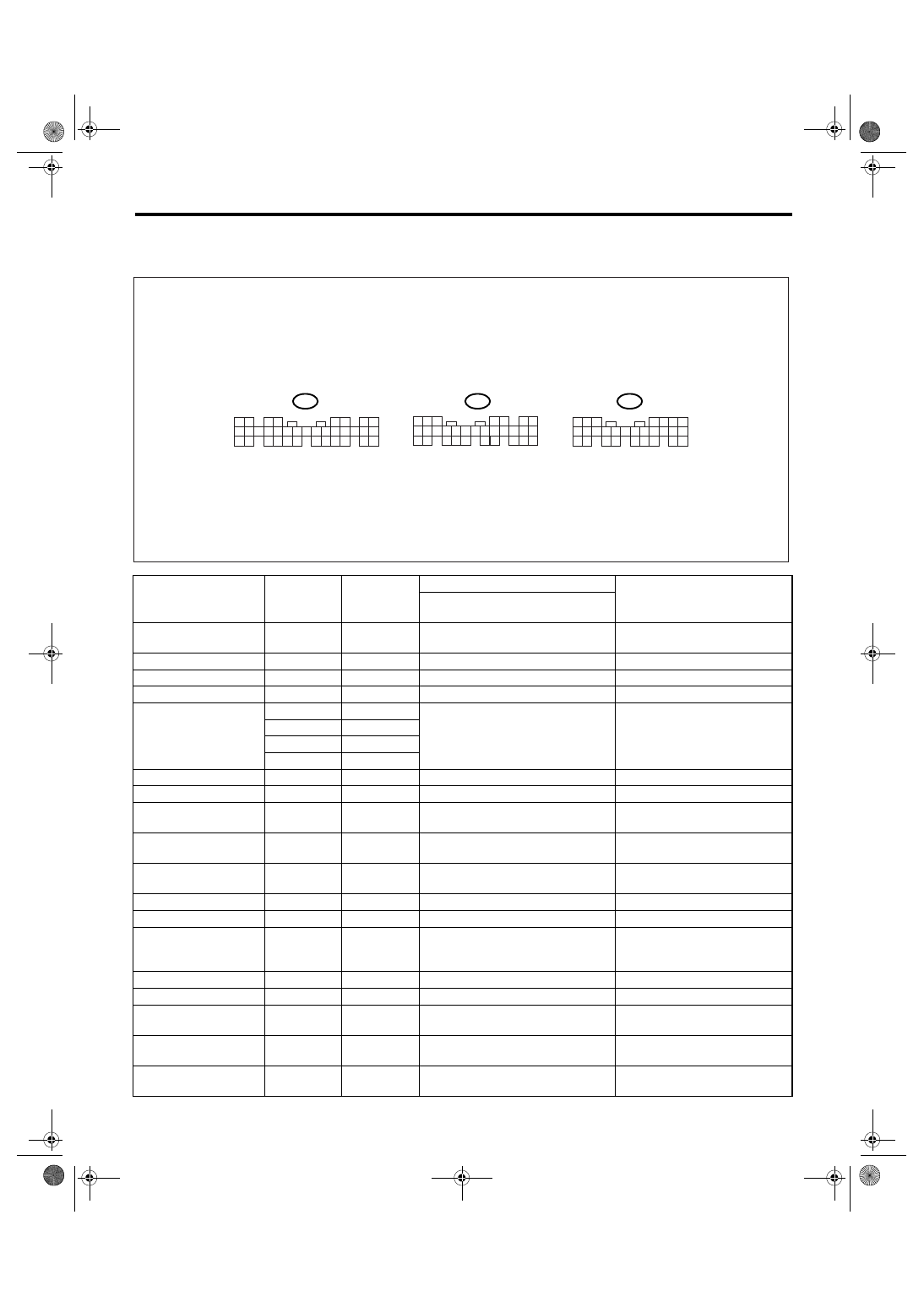
5. Control Module I/O Signal
A: ELECTRICAL SPECIFICATION
Description
Connector
No.
Terminal No.
Signal (V or
Ω)
NOTE
Ignition switch ON
(engine OFF)
System control power
supply
B281
C2
10 — 13 V
Always
Back-up power supply
B280
B7
10 — 13 V
Always
Ignition power supply
i84
A1
10 — 13 V
Ignition ON
ACC power supply
i84
A24
10 — 13 V
ACC ON
Ground
i84
A21
Less than 1
Ω
Always
B281
C9
B281
C8
B280
B22
Key warning switch
B281
C7
10 — 13 V
When ignition key inserted
Stop light switch
B281
C23
10 — 13 V
When brake pedal depressed
Illumination volume
(Vi1)
i84
A10
4.5 — 5.5 V
Small light ON
Illumination volume
(Vi2)
i84
A2
0.5 — 4.5 V
—
Illumination volume
(Vi3)
i84
A25
Less than 1
Ω
Ground circuit
Illumination output
i84
A5
10 — 13 V
Small light ON
Front fog light input
B281
C17
10 — 13 V
Front fog light ON
Rear fog light input
B281
C4
10 — 13 V
Small light ON
Front fog light ON
Rear fog light ON
Rear fog light output
B280
B13
10 — 13 V
Rear fog light ON
Headlight input
B281
C16
10 — 13 V
Headlight ON (Both Hi and Lo)
Door switch input
Driver’s seat
i84
A19
Less than 1 V (10 — 13 V at OFF)
Driver’s door open (ON)
Door switch input
Passenger’s
i84
A32
Less than 1 V (10 — 13 V at OFF)
Passenger’s door open (ON)
Door switch input
Rear RH seat
i84
A18
Less than 1 V (10 — 13 V at OFF)
Rear RH door open (ON)
LAN00012
5 6 7
8
2
1
9
4
3
10
24
22 23
25
11 12 13 14 15
26
27 28
16 17 18 19
20 21
B281
5
4
6 7
8
2
1
9
3
10
22
23
11 12 13 14 15
24 25
26 27
16 17 18
28 29
19 20
21
30
B280
i84
1 2
3 4
5 6
7 8
9 10 11 12 13 14 15 16 17 18 19 20 21 22 23
24 25
26 27 28 29
30 31 32 33
34 35
A:
B:
C:
LAN(diag)-10
LAN SYSTEM (DIAGNOSTICS)
Control Module I/O Signal
Door switch input
Rear LH seat
i84
A31
Less than 1 V (10 — 13 V at OFF)
Rear LH door open (ON)
Door switch
Trunk/Rear gate
i84
A17
Less than 1 V (10 — 13 V at OFF)
Trunk/Rear gate open (ON)
Door lock switch
i84
A16
Less than 1
Ω
All doors are locked
Illumination control
switch
i84
A30
10 — 13 (at dimmer ON)
Extinct the clock and audio illumi-
nation
Heater cock valve out-
put
B280
B15
Less than 1
Ω
When heater cock valve operates
Manual switch (LOCK)
i84
A15
Less than 1
Ω
Door lock switch ON
Manual switch
(UNLOCK)
i84
A29
Less than 1
Ω
Door lock switch ON
Door lock power supply
i84
A34
10 — 13 V
All door lock output
i84
A7
10 — 13 V
Manual, door key switch ON
All door UNLOCK out-
put
i84
A8
10 — 13 V
Manual, door key switch ON
Driver’s door lock
(Except for EK model)
i84
A23
Less than 1
Ω
When driver’s door is unlocked
Trunk/Rear gate
UNLOCK output
i84
A22
10 — 13 V
When the trunk open signal
received with keyless entry
(Sedan model)
Double lock output (EK
model)
i84
A35
Less than 1
Ω
When double lock operates
Key/shift lock power
supply
B281
C1
10 — 13 V
Shift lock output
B280
B6
10 — 13 V
Ignition switch ON, at “P” range,
foot brake ON
Wiper deicer switch
i84
A14
Less than 1
Ω
Wiper deicer switch ON
Wiper deicer relay out-
put
B280
B14
Less than 1
Ω
Wiper deicer relay ON
Rear defogger switch
i84
A28
Less than 1
Ω
Rear defogger switch ON
Rear defogger relay
output
B281
B16
Less than 1
Ω
Rear defogger relay ON
Shift switch (ON)
B281
C26
Less than 1
Ω
At Manual mode
Shift switch (UP)
B281
C15
Less than 1
Ω
At Manual mode UP
Shift switch (DOWN)
B281
C25
Less than 1
Ω
At Manual mode DOWN
“P” range switch
B281
C13
Less than 1
Ω
Impact sensor
B281
C5
Less than 1
Ω
Impact sensor ON (Model with
immobilizer)
Fuel level sensor
B281
C19
0 — 102.3
Ω
Ambient sensor
B281
C3
0.5 — 4.5 V
SIG
B281
C10
Less than 1
Ω
GND
Seat belt switch
(driver’s seat)
i84
A4
Less than 1
Ω
Driver’s seat belt worn
Seat belt switch (pas-
senger’s seat)
i84
A13
Less than 1
Ω
Passenger’s seat belt worn
Seat belt warning light
(driver’s seat)
i84
A20
Less than 1
Ω
Driver’s seat belt worn
Seat belt warning light
(passenger’s seat)
B281
C24
Less than 1
Ω
Passenger’s seat belt worn
Sedan/Wagon identifi-
cation switch
B281
C11
Sedan 10 — 13 V
Wagon 0 — 5 V
Rear wiper switch (ON)
B281
C6
Less than 1
Ω
Rear wiper switch ON
Description
Connector
No.
Terminal No.
Signal (V or
Ω)
NOTE
Ignition switch ON
(engine OFF)
Нет комментариевНе стесняйтесь поделиться с нами вашим ценным мнением.
Текст