Subaru Legacy (2005 year). Service manual — part 468
EN(H6DO)(diag)-185
ENGINE (DIAGNOSTICS)
Diagnostic Procedure with Diagnostic Trouble Code (DTC)
25
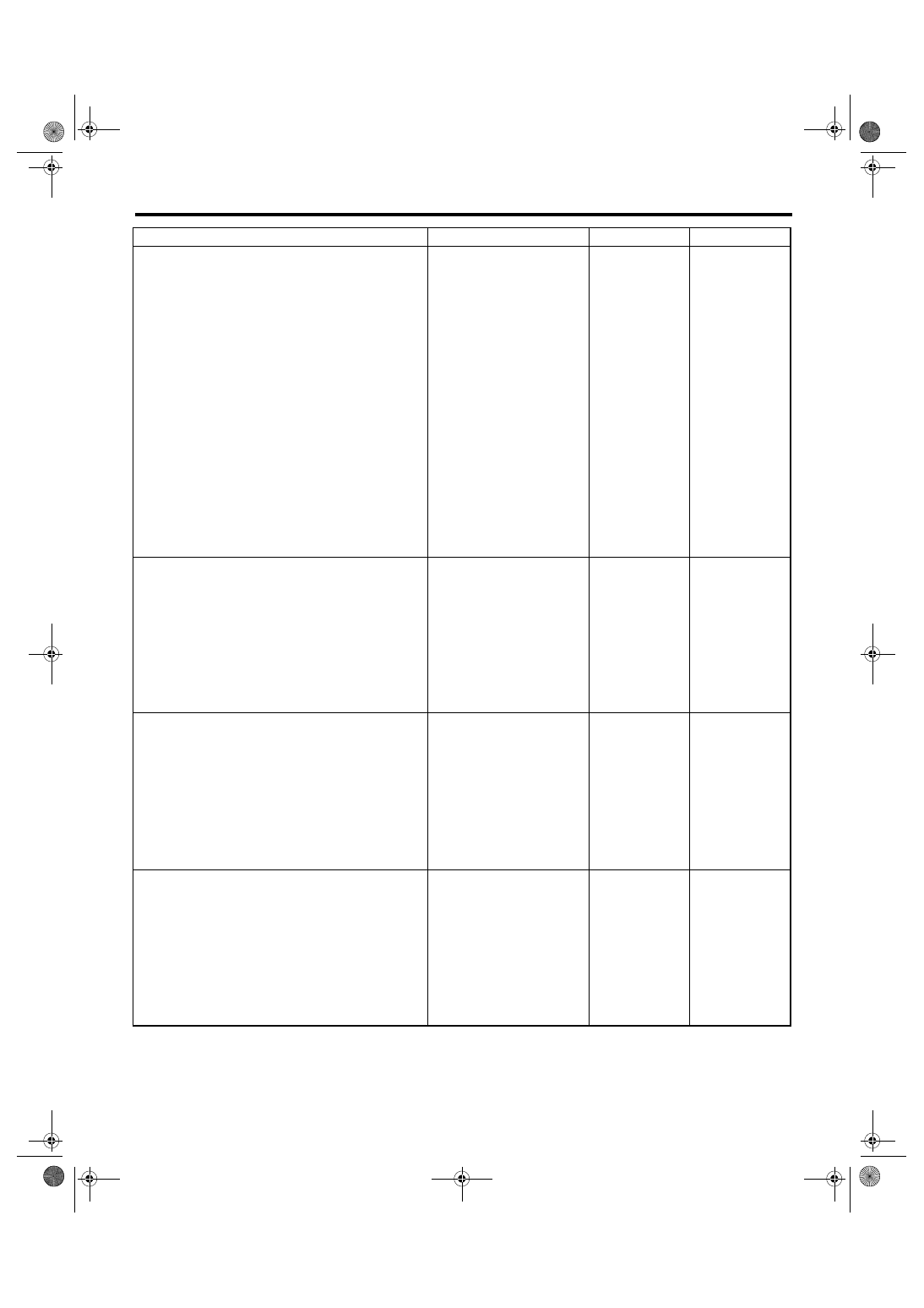
GROUP OF #5 AND #6 CYLINDERS
Are there any faults in #5 and
#6 cylinders?
Repair or replace
faulty parts.
NOTE:
• Check the fol-
lowing items.
• Spark plug
• Fuel injector
• Ignition coil
• Compres-
sion ratio
• If no abnormal is
found, check for
“IGNITION CON-
TROL SYSTEM”
of #5 and #6 cylin-
ders side. <Ref. to
EN(H6DO)(diag)-
60, IGNITION
CONTROL SYS-
TEM, Diagnostics
for Engine Start-
ing Failure.>
Inspect DTC
P0171, P0172,
P0174 or P0175
using “List of Diag-
nostic Trouble
Code (DTC)”.
<Ref. to
EN(H6DO)(diag)-
66, List of Diag-
nostic Trouble
Code (DTC).>
26
GROUP OF #1, #3 AND #5 CYLINDERS.
Are there any fault in #1, #3
and #5 cylinders?
Repair or replace
faulty parts.
NOTE:
Check the follow-
ing items.
• Spark plug
• Fuel injector
• Skipping timing
chain teeth
Inspect DTC
P0171, P0172,
P0174 or P0175
using “List of Diag-
nostic Trouble
Code (DTC)”.
<Ref. to
EN(H6DO)(diag)-
66, List of Diag-
nostic Trouble
Code (DTC).>
27
GROUP OF #2, #4 AND #6 CYLINDERS.
Are there any fault in #2, #4
and #6 cylinders?
Repair or replace
faulty parts.
NOTE:
Check the follow-
ing items.
• Spark plug
• Fuel injector
• Compression
ratio
• Skipping timing
chain teeth
Inspect DTC
P0171, P0172,
P0174 or P0175
using “List of Diag-
nostic Trouble
Code (DTC)”.
<Ref. to
EN(H6DO)(diag)-
66, List of Diag-
nostic Trouble
Code (DTC).>
28
CYLINDER AT RANDOM
Is the engine idle rough?
Inspect DTC
P0171, P0172,
P0174 or P0175
using “List of Diag-
nostic Trouble
Code (DTC)”.
<Ref. to
EN(H6DO)(diag)-
66, List of Diag-
nostic Trouble
Code (DTC).>
Repair or replace
faulty parts.
NOTE:
Check the follow-
ing items.
• Spark plug
• Fuel injector
• Compression
ratio
Step
Check
Yes
No

EN(H6DO)(diag)-186
ENGINE (DIAGNOSTICS)
Diagnostic Procedure with Diagnostic Trouble Code (DTC)
BF:DTC P0327 KNOCK SENSOR 1 CIRCUIT LOW (BANK 1 OR SINGLE SEN-
SOR)
DTC DETECTING CONDITION:
Immediately at fault recognition
TROUBLE SYMPTOM:
• Poor driving performance
• Knocking occurs.
CAUTION:
After repair or replacement of faulty parts, conduct Clear Memory Mode <Ref. to EN(H6DO)(diag)-41,
OPERATION, Clear Memory Mode.> and Inspection Mode <Ref. to EN(H6DO)(diag)-34, PROCEDURE,
Inspection Mode.>.
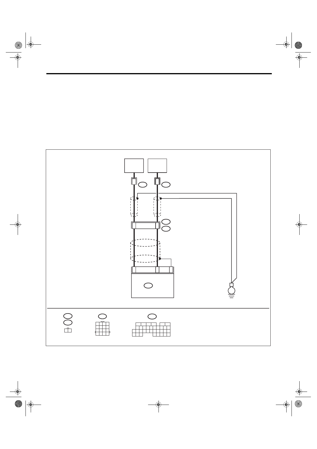
WIRING DIAGRAM:
25
33
KNOCK
SENSOR
1(RH)
13
2
ECM
B136
B20
E1
E14
E14
1 2
24
KNOCK
SENSOR
2(LH)
14
2
E48
E48
B136
5
6
7 8
2
1
9
4
3
10
24
22 23
25
11 12 13 14 15
26 27
28
16
17 18 19 20 21
33 34
29
32
30
31
35
B20
1 2 3 4
5 6 7 8
9 10 11 12
13 14 15 16
E
EN-02506
EN(H6DO)(diag)-187
ENGINE (DIAGNOSTICS)
Diagnostic Procedure with Diagnostic Trouble Code (DTC)
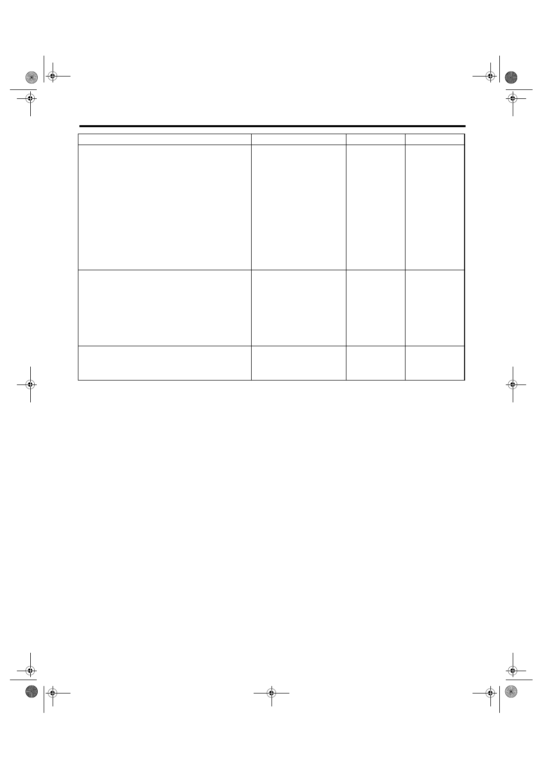
Step
Check
Yes
No
1
CHECK HARNESS BETWEEN KNOCK SEN-
SOR AND ECM CONNECTOR.
1) Turn the ignition switch to OFF.
2) Disconnect the connector from ECM.
3) Measure the resistance between ECM har-
ness connector and chassis ground.
Connector & terminal
(B136) No. 25 — Chassis ground:
Is the resistance more than
700 k
Ω?
Repair the har-
ness and connec-
tor.
NOTE:
In this case, repair
the following:
• Open circuit of
harness between
knock sensor and
ECM connector
• Poor contact in
knock sensor con-
nector
• Poor contact in
coupling connector
2
CHECK KNOCK SENSOR.
1) Disconnect the connector from knock sen-
sor.
2) Measure the resistance between knock
sensor connector terminal and engine ground.
Terminal
No. 2 — Engine ground:
Is the resistance more than
700 k
Ω?
Repair the har-
ness and connec-
tor.
NOTE:
In this case, repair
the following:
• Poor contact in
knock sensor con-
nector
3
CHECK CONDITION OF KNOCK SENSOR
INSTALLATION.
Is the knock sensor installation
bolt tightened securely?
Replace the knock
sensor. <Ref. to
FU(H6DO)-21,
Knock Sensor.>
Tighten the knock
sensor installation
bolt securely.
EN(H6DO)(diag)-188
ENGINE (DIAGNOSTICS)
Diagnostic Procedure with Diagnostic Trouble Code (DTC)
BG:DTC P0328 KNOCK SENSOR 1 CIRCUIT HIGH (BANK 1 OR SINGLE SEN-
SOR)
DTC DETECTING CONDITION:
Immediately at fault recognition
TROUBLE SYMPTOM:
• Poor driving performance
• Knocking occurs.
CAUTION:
After repair or replacement of faulty parts, conduct Clear Memory Mode <Ref. to EN(H6DO)(diag)-41,
OPERATION, Clear Memory Mode.> and Inspection Mode <Ref. to EN(H6DO)(diag)-34, PROCEDURE,
Inspection Mode.>.
WIRING DIAGRAM:
25
33
KNOCK
SENSOR
1(RH)
13
2
ECM
B136
B20
E1
E14
E14
1 2
24
KNOCK
SENSOR
2(LH)
14
2
E48
E48
B136
5
6
7 8
2
1
9
4
3
10
24
22 23
25
11 12 13 14 15
26 27
28
16
17 18 19 20 21
33 34
29
32
30
31
35
B20
1 2 3 4
5 6 7 8
9 10 11 12
13 14 15 16
E
EN-02506
Нет комментариевНе стесняйтесь поделиться с нами вашим ценным мнением.
Текст