Subaru Legacy (2005 year). Service manual — part 148
EN(H4SO 2.0)(diag)-181
ENGINE (DIAGNOSTICS)
Diagnostic Procedure with Diagnostic Trouble Code (DTC)
BK:DTC P1498 EGR SOLENOID VALVE SIGNAL #4 CIRCUIT MALFUNCTION
(LOW INPUT)
DTC DETECTING CONDITION:
Immediately at fault recognition
TROUBLE SYMPTOM:
• Erroneous idling
• Poor driving performance
• Engine breathing
CAUTION:
After repair or replacement of faulty parts, perform Clear Memory Mode <Ref. to EN(H4SO 2.0)(diag)-
38, OPERATION, Clear Memory Mode.> and Inspection Mode <Ref. to EN(H4SO 2.0)(diag)-32, PRO-
CEDURE, Inspection Mode.>.
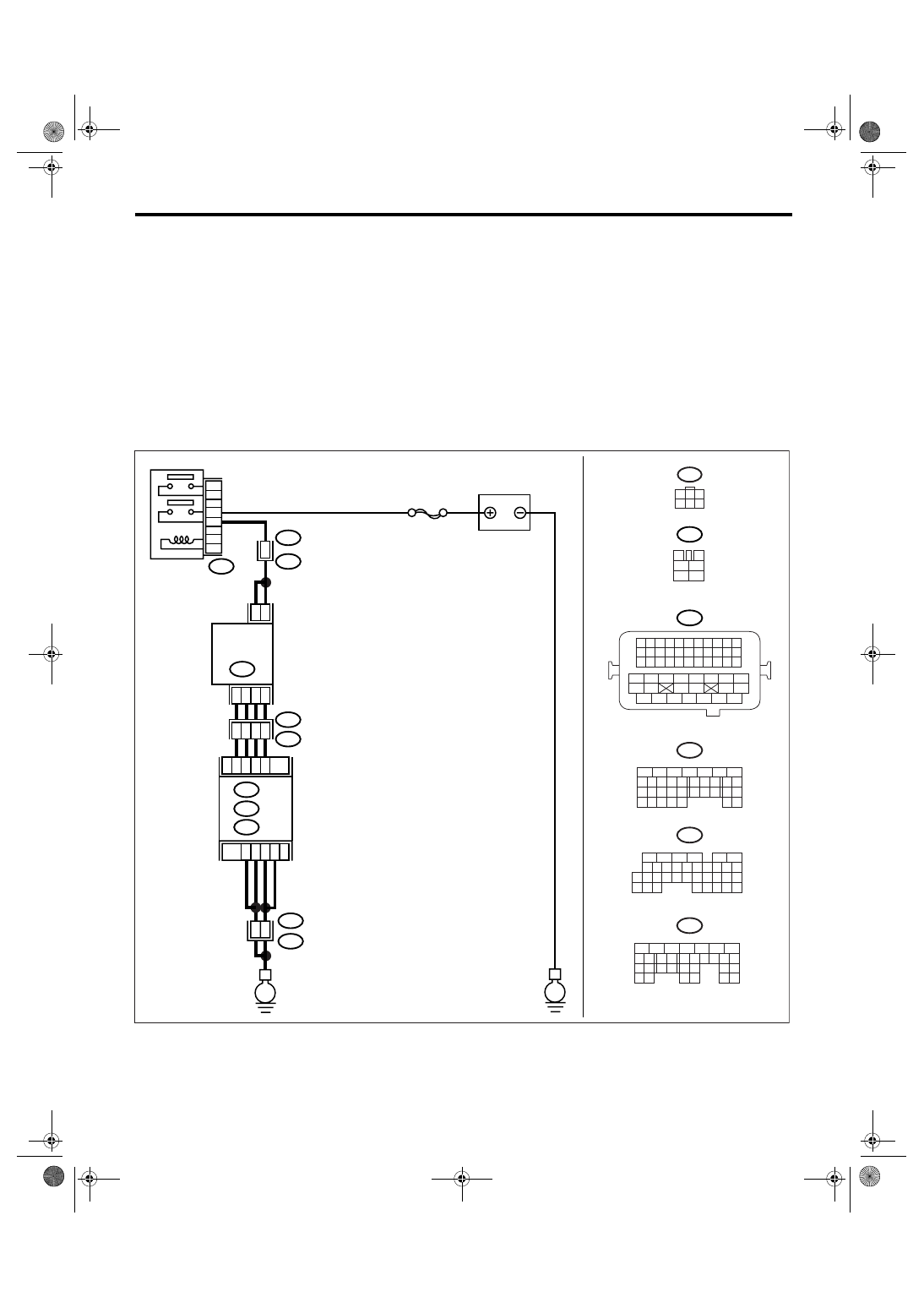
WIRING DIAGRAM:
EN-03483
E
E
B47
E18
2
5
1
4
3
6
B21
E2
B21
E2
B21
E2
5
3
6
4
2
1
48
26
A12
A3
A13
A4
C6
C5
D1
25
29
30
35
36
SBF-7
BATTERY
MAIN RELAY
EGR
VALVE
A: B134
C: B136
D: B137
ECM
B47
3
4
1
2
5
6
A2
B21
1 2 3 4
12 13 14 15
5 6 7 8
16 17 18 19
9 10 11
20 21 22
23 24 25 26 27 28 29 30 31 32 33
35
34
37
36
39
38
41
40
43
42
44
45
47
46
49
48
51
50
53
52
54
B137
5
6
7
8
2
1
9
4
3
10
22 23
11 12 13 14 15
24 25
26
16 17
18 19 20 21
27
28 29
30 31
B134
5
6
7
8
2
1
9
4
3
10
24
22 23
25
11 12 13 14 15
26 27
28
16 17
18 19 20 21
33 34
29
32
30 31
A:
D:
B136
5
6
7 8
2
1
9
4
3
10
24
22 23
25
11 12 13 14 15
26 27
28
16
17 18 19 20 21
33 34
29
32
30
31
35
C:
1
3
4 5 6
2
E18
EN(H4SO 2.0)(diag)-182
ENGINE (DIAGNOSTICS)
Diagnostic Procedure with Diagnostic Trouble Code (DTC)
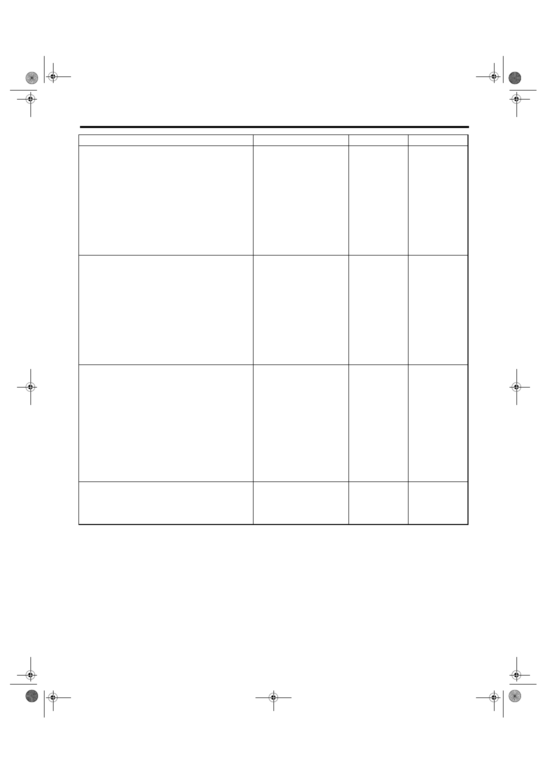
Step
Check
Yes
No
1
CHECK POWER SUPPLY TO EGR SOLE-
NOID VALVE.
1) Turn the ignition switch to OFF.
2) Disconnect the connector from EGR sole-
noid valve.
3) Turn the ignition switch to ON.
4) Measure the voltage between EGR sole-
noid valve connector and engine ground.
Connector & terminal
(E18) No. 2 (+) — Engine ground (
−
):
(E18) No. 5 (+) — Engine ground (
−
):
Is the voltage more than 10 V? Go to step 2.
Repair the har-
ness and connec-
tor.
NOTE:
In this case, repair
the following item:
• Open circuit of
harness between
EGR solenoid
valve and main
relay connector
• Poor contact in
coupling connector
2
CHECK HARNESS BETWEEN ECM AND
EGR SOLENOID VALVE CONNECTOR.
1) Turn the ignition switch to OFF.
2) Measure the resistance between ECM and
EGR solenoid valve connector.
Connector & terminal
DTC P1492; (B134) No. 13 — (E18) No. 3:
DTC P1494; (B134) No. 12 — (E18) No. 1:
DTC P1496; (B134) No. 3 — (E18) No. 4:
DTC P1498; (B134) No. 4 — (E18) No. 6:
Is the resistance less than 1
Ω?
Repair the har-
ness and connec-
tor.
NOTE:
In this case, repair
the following item:
• Open circuit of
harness between
ECM and EGR
solenoid valve
connector
• Poor contact in
coupling connector
3
CHECK HARNESS BETWEEN ECM AND
EGR SOLENOID VALVE CONNECTOR.
1) Disconnect the connector from ECM.
2) Measure the resistance between ECM con-
nector and chassis ground.
Connector & terminal
DTC P1492; (B134) No. 13 — Chassis
ground:
DTC P1494; (B134) No. 12 — Chassis
ground:
DTC P1496; (B134) No. 3 — Chassis
ground:
DTC P1498; (B134) No. 4 — Chassis
ground:
Is the resistance more than 1
M
Ω?
Repair the ground
short circuit in har-
ness between
ECM and EGR
solenoid valve
connector.
4
CHECK POOR CONTACT.
Check poor contact in ECM connector and
EGR solenoid valve connector.
Is there poor contact in ECM
connector or EGR solenoid
valve connector?
Repair the poor
contact in ECM
connector or EGR
solenoid valve
connector.
Replace the EGR
solenoid valve.
<Ref. to FU(H4SO
2.0)-28, EGR
Valve.>

EN(H4SO 2.0)(diag)-183
ENGINE (DIAGNOSTICS)
Diagnostic Procedure with Diagnostic Trouble Code (DTC)
BL:DTC P1499 EGR SOLENOID VALVE SIGNAL #4 CIRCUIT MALFUNCTION
(HIGH INPUT)
DTC DETECTING CONDITION:
Immediately at fault recognition
TROUBLE SYMPTOM:
• Erroneous idling
• Poor driving performance
• Engine breathing
CAUTION:
After repair or replacement of faulty parts, perform Clear Memory Mode <Ref. to EN(H4SO 2.0)(diag)-
38, OPERATION, Clear Memory Mode.> and Inspection Mode <Ref. to EN(H4SO 2.0)(diag)-32, PRO-
CEDURE, Inspection Mode.>.
WIRING DIAGRAM:
EN-03483
E
E
B47
E18
2
5
1
4
3
6
B21
E2
B21
E2
B21
E2
5
3
6
4
2
1
48
26
A12
A3
A13
A4
C6
C5
D1
25
29
30
35
36
SBF-7
BATTERY
MAIN RELAY
EGR
VALVE
A: B134
C: B136
D: B137
ECM
B47
3
4
1
2
5
6
A2
B21
1 2 3 4
12 13 14 15
5 6 7 8
16 17 18 19
9 10 11
20 21 22
23 24 25 26 27 28 29 30 31 32 33
35
34
37
36
39
38
41
40
43
42
44
45
47
46
49
48
51
50
53
52
54
B137
5
6
7
8
2
1
9
4
3
10
22 23
11 12 13 14 15
24 25
26
16 17
18 19 20 21
27
28 29
30 31
B134
5
6
7
8
2
1
9
4
3
10
24
22 23
25
11 12 13 14 15
26 27
28
16 17
18 19 20 21
33 34
29
32
30 31
A:
D:
B136
5
6
7 8
2
1
9
4
3
10
24
22 23
25
11 12 13 14 15
26 27
28
16
17 18 19 20 21
33 34
29
32
30
31
35
C:
1
3
4 5 6
2
E18
EN(H4SO 2.0)(diag)-184
ENGINE (DIAGNOSTICS)
Diagnostic Procedure with Diagnostic Trouble Code (DTC)
BM:DTC P1518 STARTER SWITCH CIRCUIT LOW INPUT
DTC DETECTING CONDITION:
Detects when malfunction occurs in 2 continuous driving cycles.
TROUBLE SYMPTOM:
Failure of engine to start
CAUTION:
After repair or replacement of faulty parts, perform Clear Memory Mode <Ref. to EN(H4SO 2.0)(diag)-
38, OPERATION, Clear Memory Mode.> and Inspection Mode <Ref. to EN(H4SO 2.0)(diag)-32, PRO-
CEDURE, Inspection Mode.>.
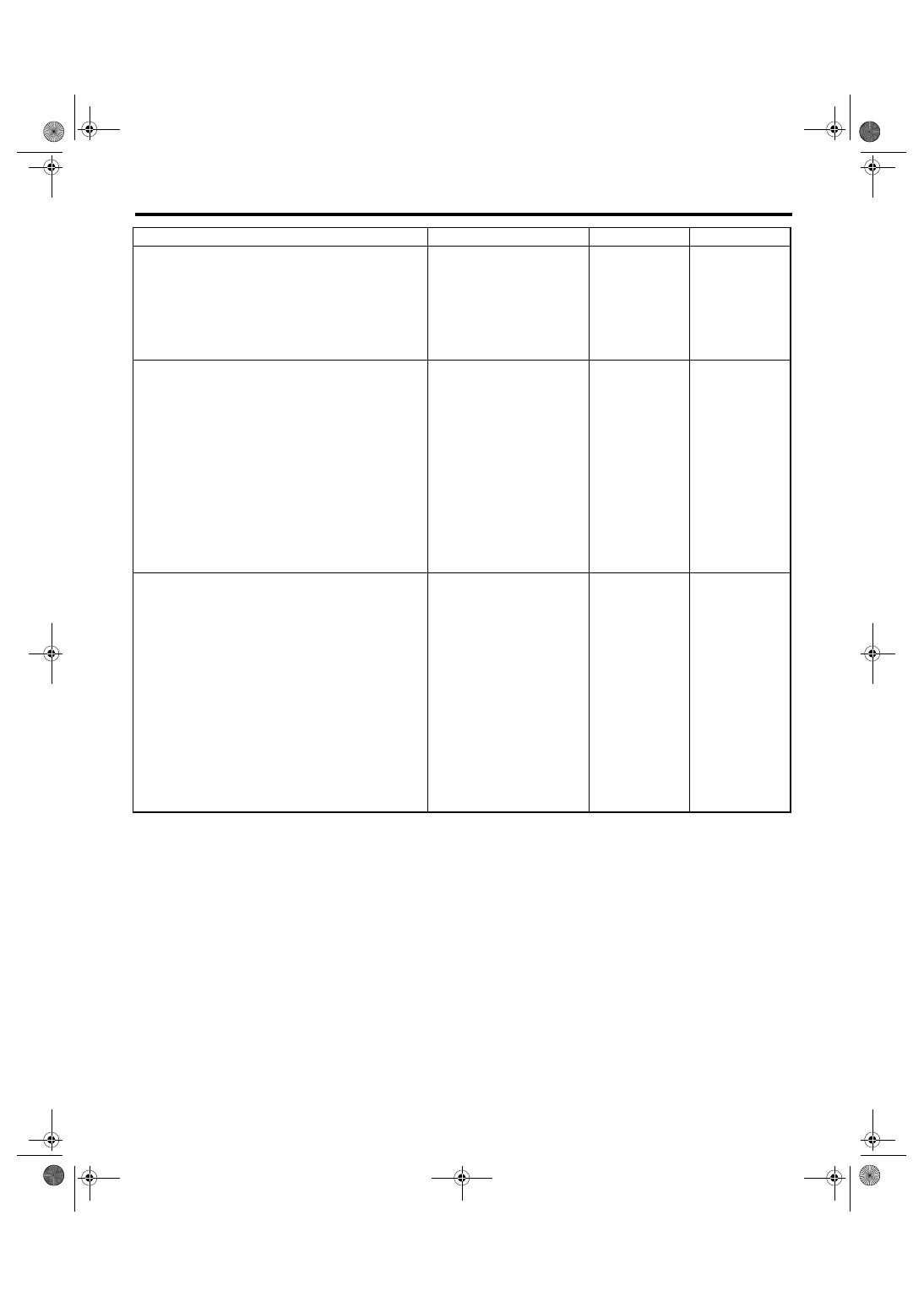
Step
Check
Yes
No
1
CHECK ANY OTHER DTC ON DISPLAY.
Is any other DTC displayed?
Check DTC using
“List of Diagnostic
Trouble Code
(DTC)”. <Ref. to
EN(H4SO
2.0)(diag)-64, List
of Diagnostic Trou-
ble Code (DTC).>
2
CHECK GROUND CIRCUIT FOR ECM.
1) Turn the ignition switch to OFF.
2) Measure the resistance between ECM con-
nector and chassis ground.
Connector & terminal
(B134) No. 2 — Chassis ground:
(B136) No. 5 — Chassis ground:
(B136) No. 6 — Chassis ground:
(B137) No. 1 — Chassis ground:
Is the resistance less than 5
Ω?
Repair the har-
ness and connec-
tor.
NOTE:
In this case, repair
the following item:
• Open circuit of
harness between
ECM connector
and engine ground
terminal
• Poor contact in
ECM connector
• Poor contact in
coupling connector
3
CHECK HARNESS BETWEEN ECM AND
EGR SOLENOID VALVE CONNECTOR.
1) Turn the ignition switch to OFF.
2) Disconnect the connector from EGR sole-
noid valve.
3) Turn the ignition switch to ON.
4) Measure the voltage between ECM con-
nector and chassis ground.
Connector & terminal
DTC P1493; (B134) No. 13 (+) — Chassis
ground (
−
):
DTC P1495; (B134) No. 12 (+) — Chassis
ground (
−
):
DTC P1497; (B134) No. 3 (+) — Chassis
ground (
−
):
DTC P1499; (B134) No. 4 (+) — Chassis
ground (
−
):
Is the voltage more than 10 V? Repair the battery
short circuit in har-
ness between
ECM and EGR
solenoid valve
connector. After
repair, replace the
ECM. <Ref. to
FU(H4SO 2.0)-34,
Engine Control
Module (ECM).>
Replace the ECM.
<Ref. to FU(H4SO
2.0)-34, Engine
Control Module
(ECM).>
Нет комментариевНе стесняйтесь поделиться с нами вашим ценным мнением.
Текст