Subaru Legacy (2005 year). Service manual — part 146
EN(H4SO 2.0)(diag)-173
ENGINE (DIAGNOSTICS)
Diagnostic Procedure with Diagnostic Trouble Code (DTC)
2. MT MODEL
DTC DETECTING CONDITION:
Detects when malfunction occurs in 2 continuous driving cycles.
TROUBLE SYMPTOM:
Erroneous idling
CAUTION:
After repair or replacement of faulty parts, perform Clear Memory Mode <Ref. to EN(H4SO 2.0)(diag)-
38, OPERATION, Clear Memory Mode.> and Inspection Mode <Ref. to EN(H4SO 2.0)(diag)-32, PRO-
CEDURE, Inspection Mode.>.
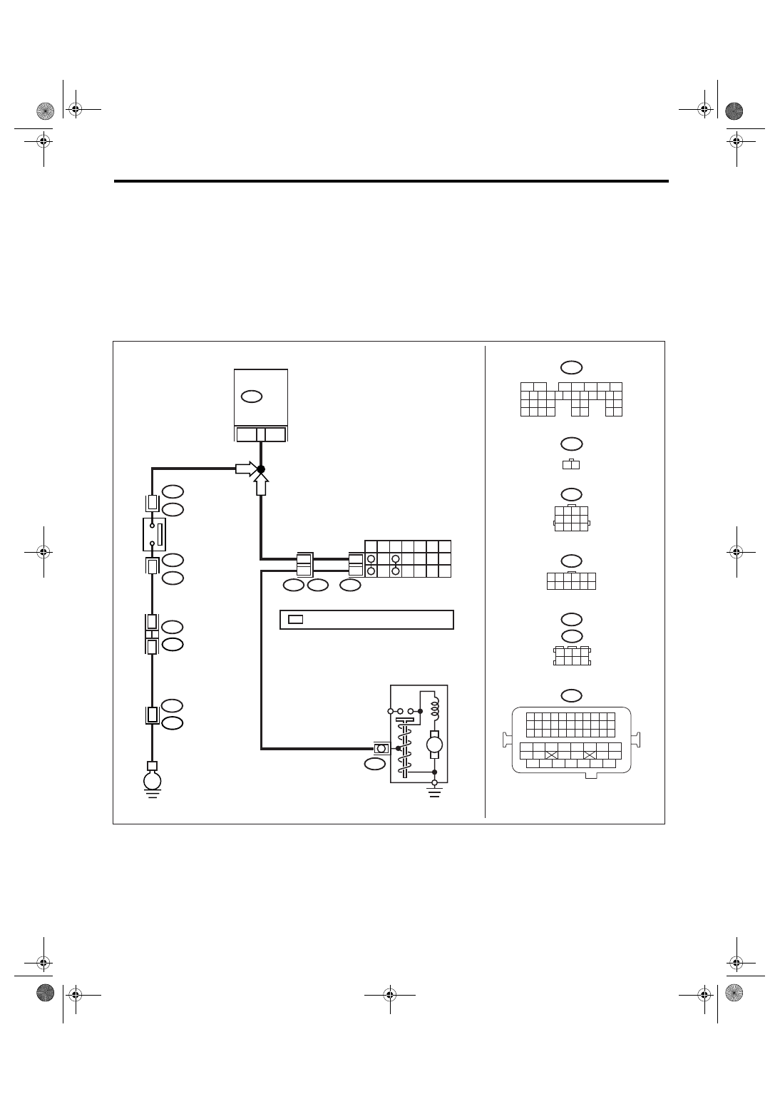
WIRING DIAGRAM:
B12
T3
B14
T7
INHIBITOR SWITCH
NEUTRAL
POSITION
SWITCH
STARTER MOTOR
P
R
N
D
3
2
1
7
12
11
12
B135
ECM
12
B12
T7
1 2 3 4 5 6
7 8 9 10 11 12
1 2 3 4
5 6 7 8
9 10 11 12
E
1
B25
T2
T2
B25
2
MT
AT
EN-03485
M
36
B135
5
6
7
8
2
1
9
4
3
10
24
22 23
25
11 12 13 14 15
26 27
28
16 17 18 19
20 21
29 30 31
32 33
34 35
B21
1 2 3 4
12 13 14 15
5 6 7 8
16 17 18 19
9 10 11
20 21 22
23 24 25 26 27 28 29 30 31 32 33
35
34
37
36
39
38
41
40
43
42
44
45
47
46
49
48
51
50
53
52
54
B25
1 2
1 2 3 4
5 6 7 8
B83 : RHD
B122 : LHD
*
: TERMINAL No. RANDOM ARRANGEMENT
B83
B122 : LHD
: RHD
E2
B21
*
*
EN(H4SO 2.0)(diag)-174
ENGINE (DIAGNOSTICS)
Diagnostic Procedure with Diagnostic Trouble Code (DTC)
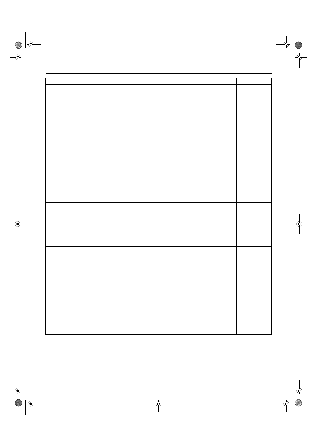
Step
Check
Yes
No
1
CHECK INPUT SIGNAL OF ECM.
1) Turn the ignition switch to ON.
2) Place the shift lever except in neutral.
3) Measure the voltage between ECM and
chassis ground.
Connector & terminal
(B135) No. 12 (+) — Chassis ground (
−
):
Is the voltage more than 10 V? Go to step 2.
2
CHECK INPUT SIGNAL OF ECM.
1) Place the shift lever in neutral.
2) Measure the voltage between ECM and
chassis ground.
Connector & terminal
(B135) No. 12 (+) — Chassis ground (
−
):
Is the voltage less than 1 V?
3
CHECK POOR CONTACT.
Check poor contact in ECM connector.
Is there poor contact in ECM
connector?
Repair the poor
contact in ECM
connector.
Replace the ECM.
<Ref. to FU(H4SO
2.0)-34, Engine
Control Module
(ECM).>
4
CHECK NEUTRAL POSITION SWITCH.
1) Place the shift lever except in neutral.
2) Measure the resistance between transmis-
sion harness connector terminals.
Connector & terminal
(T2) No. 1 — No. 2:
Is the resistance less than 1
Ω?
Repair the open
circuit in transmis-
sion harness or
replace the neu-
tral position switch.
5
CHECK HARNESS BETWEEN ECM AND
NEUTRAL POSITION SWITCH CONNEC-
TOR.
1) Disconnect the connector from ECM.
2) Measure the resistance of harness
between ECM and transmission harness con-
nector.
Connector & terminal
(B135) No. 12 — (B25) No. 2:
Is the resistance less than 1
Ω?
Repair the open
circuit of harness
between ECM and
transmission har-
ness connector.
6
CHECK HARNESS BETWEEN ECM AND
NEUTRAL POSITION SWITCH CONNEC-
TOR.
Measure the resistance of harness between
transmission harness connector and engine
ground.
Connector & terminal
(B25) No. 1 — Engine ground:
Is the resistance less than 5
Ω?
Repair the har-
ness and connec-
tor.
NOTE:
In this case, repair
the following item:
• Open circuit of
harness between
transmission har-
ness connector
and engine ground
• Poor contact in
coupling connector
7
CHECK POOR CONTACT.
Check poor contact in transmission harness
connector.
Is there poor contact in trans-
mission harness connector.
Repair poor con-
tact in transmis-
sion harness
connector.
Replace the ECM.
<Ref. to FU(H4SO
2.0)-34, Engine
Control Module
(ECM).>
EN(H4SO 2.0)(diag)-175
ENGINE (DIAGNOSTICS)
Diagnostic Procedure with Diagnostic Trouble Code (DTC)
BB:DTC P1134 A/F SENSOR MICRO-COMPUTER PROBLEM
DTC DETECTING CONDITION:
Immediately at fault recognition
CAUTION:
After repair or replacement of faulty parts, perform Clear Memory Mode <Ref. to EN(H4SO 2.0)(diag)-
38, OPERATION, Clear Memory Mode.> and Inspection Mode <Ref. to EN(H4SO 2.0)(diag)-32, PRO-
CEDURE, Inspection Mode.>.
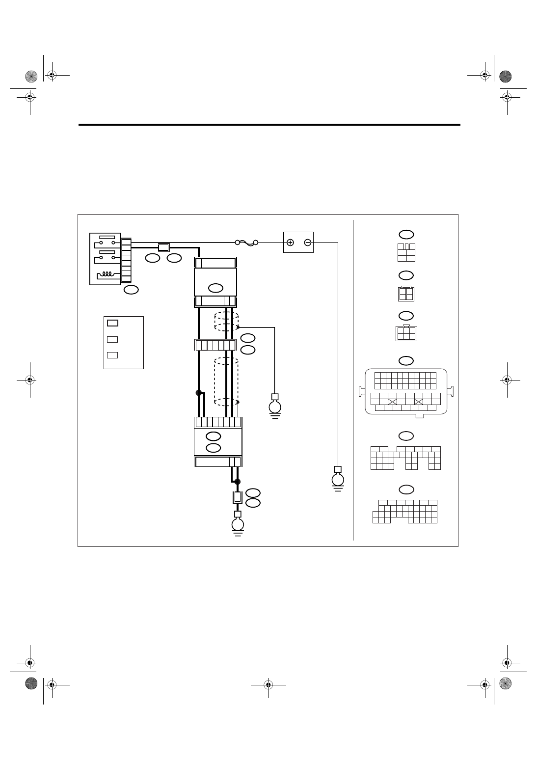
WIRING DIAGRAM:
EN-03475
3
4
1
2
5
6
B47
SBF-5
E
B47
E24
5
3
4
6
2
1
C34
C35
C33
B3
B2
B1
B135
E
B5
B6
52
B21
E2
B21
E2
50
51
3
4
E2
B21
E
B21
1 2 3 4
12 13 14 15
5 6 7 8
16 17 18 19
9 10 11
20 21 22
23 24 25 26 27 28 29 30 31 32 33
35
34
37
36
39
38
41
40
43
42
44
45
47
46
49
48
51
50
53
52
54
E24
ECM
BATTERY
FRONT OXYGEN
(A/F) SENSOR
MAIN RELAY
B136
B:
C:
1
2
3
4
B135
5
6
7
8
2
1
9
4
3
10
24
22 23
25
11 12 13 14 15
26 27
28
16 17 18 19
20 21
29 30 31
32 33
34 35
B:
B136
5
6
7 8
2
1
9
4
3
10
24
22 23
25
11 12 13 14 15
26 27
28
16
17 18 19 20 21
33 34
29
32
30
31
35
C:
E24
3
2
*
1
*
*
3
LHD : 4
RHD : 1
*
1
*
*
2
3
3
1
6 5 4
2
: RHD
: LHD
LHD : 1
RHD : 4
LHD : 2
RHD : 6
EN(H4SO 2.0)(diag)-176
ENGINE (DIAGNOSTICS)
Diagnostic Procedure with Diagnostic Trouble Code (DTC)
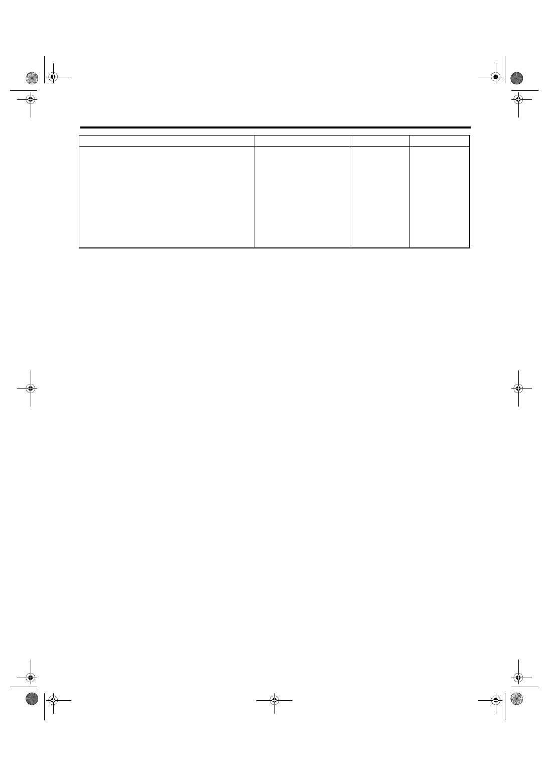
Step
Check
Yes
No
1
CHECK ANY OTHER DTC ON DISPLAY.
Is any other DTC displayed?
Check DTC using
“List of Diagnostic
Trouble Code
(DTC)”. <Ref. to
EN(H4SO
2.0)(diag)-64, List
of Diagnostic Trou-
ble Code (DTC).>
NOTE:
It is not necessary
to inspect DTC
P1134.
Replace the ECM.
<Ref. to FU(H4SO
2.0)-34, Engine
Control Module
(ECM).>
Нет комментариевНе стесняйтесь поделиться с нами вашим ценным мнением.
Текст