Subaru Legacy (2005 year). Service manual — part 149
EN(H4SO 2.0)(diag)-185
ENGINE (DIAGNOSTICS)
Diagnostic Procedure with Diagnostic Trouble Code (DTC)
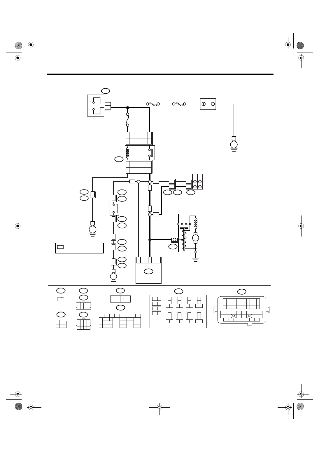
WIRING DIAGRAM:
EN-03471
B225
10
11 12
13
14
15 16
17
18
19 20
21
22
23 24
25
26
27 28
29
30
31 32
33
34
35 36
39 40
37
38
1
2
9
3
4
5
6
7
8
B12
1 2 3 4
5 6 7 8
9 10 11 12
B25
1 2
1 2 3 4
5 6 7 8
B83
B122
T7
1 2 3 4 5 6
7 8 9 10 11 12
B135
1
2
7
8 9
5
6
3
4
10 11 12
19
20 21
29 30 31
13 14 15 16 17
27
28
18
22 23
24 25
26
32 33
34 35
B21
1 2 3 4
12 13 14 15
5 6 7 8
16 17 18 19
9 10 11
20 21 22
23 24 25 26 27 28 29 30 31 32 33
35
34
37
36
39
38
41
40
43
42
44
45
47
46
49
48
51
50
53
52
54
B72
1
3
4 5 6
2
23
ECM
B135
B14
M
STARTER MOTOR
E
12
12
B12
T3
T7
P
N
7
11
AT
AT
MT
MT
No.21
MAIN SBF
SBF-6
E
B72
2
3
BATTERY
IGNITION
SWITCH
B225
16
14
16
14
STARTER
RELAY
15
13
15
13
LHD
RHD
LHD
RHD
MT
12
B21
E2
E
36
NEUTRAL
POSITION
SWITCH
1
B25
T2
T2
B25
2
*
B83
B122 : LHD
: RHD
JOINT
CONNECTOR
*
B21
E2
35
*
: TERMINAL No. RANDOM
ARRANGEMENT
EN(H4SO 2.0)(diag)-186
ENGINE (DIAGNOSTICS)
Diagnostic Procedure with Diagnostic Trouble Code (DTC)
Step
Check
Yes
No
1
CHECK OPERATION OF STARTER MOTOR.
Turn the ignition switch to START.
NOTE:
• For AT model, set the selector lever in the
“P” or “N” range.
• For MT model, depress the clutch pedal.
Does the starter motor oper-
ate?
Repair the har-
ness and connec-
tor.
NOTE:
In this case, repair
the following item:
• Open or ground
short circuit of har-
ness between
ECM and starter
motor connector
• Poor contact in
ECM connector
Check the starter
motor circuit. <Ref.
to EN(H4SO
2.0)(diag)-51,
STARTER
MOTOR CIRCUIT,
Diagnostics for
Engine Starting
Failure.>
EN(H4SO 2.0)(diag)-187
ENGINE (DIAGNOSTICS)
Diagnostic Procedure with Diagnostic Trouble Code (DTC)
BN:DTC P1521 BRAKE CIRCUIT RANGE/PERFORMANCE PROBLEM(HIGH IN-
PUT)
DTC DETECTING CONDITION:
Immediately at fault recognition
CAUTION:
After repair or replacement of faulty parts, perform Clear Memory Mode <Ref. to EN(H4SO 2.0)(diag)-
38, OPERATION, Clear Memory Mode.> and Inspection Mode <Ref. to EN(H4SO 2.0)(diag)-32, PRO-
CEDURE, Inspection Mode.>.
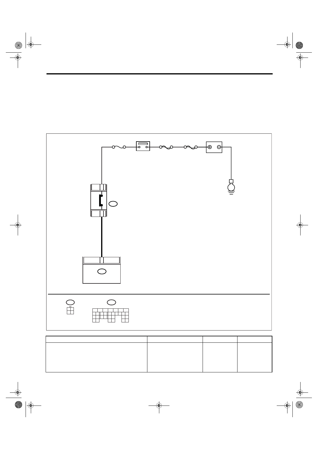
WIRING DIAGRAM:
Step
Check
Yes
No
1
CHECK INPUT SIGNAL OF ECM.
1) Turn the ignition switch to ON.
2) Measure the voltage between ECM and
chassis ground.
Connector & terminal
(B137) No. 12 (+) — Chassis ground (
−
):
Is the voltage more than 10 V? Go to step 2.
EN-03510
12
No.4
B65
MAIN SBF
SBF-8
E
4
1
ECM
B137
BATTERY
BREKE SWITCH
B65
3 4
1 2
B137
5
6
7
8
2
1
9
4
3
10
22 23
11 12 13 14 15
24 25
26
16 17
18 19 20 21
27
28 29
30 31
EN(H4SO 2.0)(diag)-188
ENGINE (DIAGNOSTICS)
Diagnostic Procedure with Diagnostic Trouble Code (DTC)
2
CHECK INPUT SIGNAL OF ECM.
1) Turn the ignition switch to ON.
2) Measure the voltage between ECM and
chassis ground with brake pedal depressed.
Connector & terminal
(B137) No. 12 (+) — Chassis ground (
−
):
Is the voltage more than 10 V? Repair the battery
short circuit
between ECM and
brake switch.
3
CHECK BRAKE SWITCH.
1) Turn the ignition switch to OFF.
2) Measure the resistance between brake
switch connectors.
Terminals
(B65) No. 1 — (B65) No. 4:
Is the resistance less than 1
Ω?
Replace the brake
switch. <Ref. to
CC-6, Stop Light &
Brake Switch.>
4
CHECK BRAKE SWITCH.
Measure the resistance between brake switch
connectors with brake pedal depressed.
Terminals
(B65) No. 1 — (B65) No. 4:
Is the resistance more than 1
M
Ω?
Check poor con-
tact in ECM con-
nector.
Replace the brake
switch. <Ref. to
CC-6, Stop Light &
Brake Switch.>
Step
Check
Yes
No
Нет комментариевНе стесняйтесь поделиться с нами вашим ценным мнением.
Текст