Subaru Legacy (2005 year). Service manual — part 92
LU(H4SO 2.0)-13
LUBRICATION
Oil Pump
CAUTION:
Before disassembling the oil pump, remove the
relief valve.
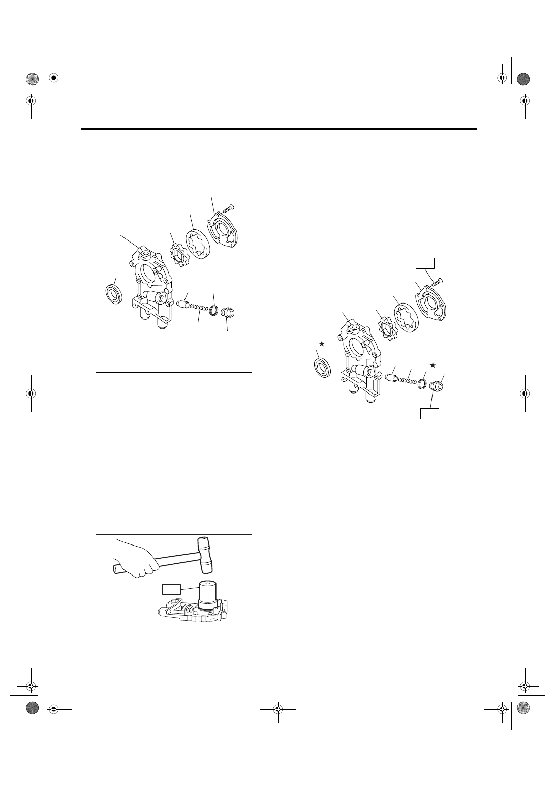
D: ASSEMBLY
1) Install the front oil seal using ST.
ST
499587100
OIL SEAL INSTALLER
NOTE:
Use a new oil seal.
2) Apply a coat of engine oil to inner and outer ro-
tors.
3) Install the inner and outer rotors in their original
positions.
4) Install the oil relief valve and relief valve spring
and plug.
NOTE:
Use a new gasket.
5) Install the oil pump cover.
Tightening torque:
T1: 5.4 N
⋅
m (0.55 kgf-m, 4.0 ft-lb)
T2: 44 N
⋅
m (4.5 kgf-m, 32.5 ft-lb)
(A) Oil seal
(B) Oil pump case
(C) Inner rotor
(D) Outer rotor
(E) Oil pump cover
(F) Relief valve
(G) Relief valve spring
(H) Plug
(I) Gasket
LU-00020
(E)
(D)
(C)
(B)
(A)
(F)
(G)
(I)
(H)
LU-00021
ST
(A) Oil seal
(B) Oil pump case
(C) Inner rotor
(D) Outer rotor
(E) Oil pump cover
(F) Relief valve
(G) Relief valve spring
(H) Plug
(I) Gasket
LU-02134
T1
T2
(G)
(F)
(I)
(H)
(A)
(B)
(C)
(D)
(E)
LU(H4SO 2.0)-14
LUBRICATION
Oil Pump
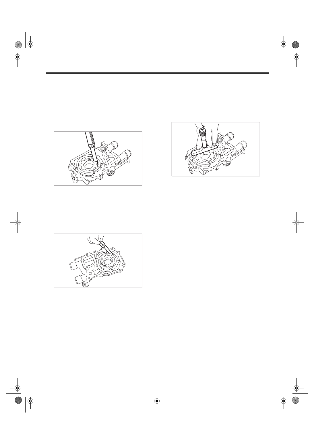
E: INSPECTION
1. TIP CLEARANCE
Measure the tip clearance of rotors. If the clearance
is out of the specification, replace rotors as a
matched set.
Tip clearance:
Specification
0.04 — 0.14 mm (0.0016 — 0.0055 in)
2. CASE CLEARANCE
Measure the clearance between the outer rotor and
oil pump rotor housing. If the clearance is out of the
specification, replace the oil pump case.
Case clearance:
Specification
0.10 — 0.175 mm (0.0039 — 0.0069 in)
3. SIDE CLEARANCE
Measure the clearance between oil pump inner ro-
tor and pump cover. If the clearance is out of the
specification, replace rotor or oil pump case.
Side clearance:
Specification
0.02 — 0.07 mm (0.0008 — 0.0028 in)
4. OIL RELIEF VALVE
Check the valve for fitting condition and damage,
and the relief valve spring for damage and deterio-
ration. Replace the parts if defective.
Relief valve spring:
Free length
72.8 mm (2.866 in)
Installed length
54.7 mm (2.154 in)
Load when installed
81.3 N (8.29 kgf, 18.24 lbf)
5. OIL PUMP CASE
Check the worn shaft hole, clogged oil passage,
worn rotor chamber, cracks and other faults.
6. OIL SEAL
Check the oil seal lips for deformation, hardening,
wear, etc., and replace if defective.
LU-00023
LU-00024
LU-00025
LU(H4SO 2.0)-15
LUBRICATION
Oil Pan and Strainer
5. Oil Pan and Strainer
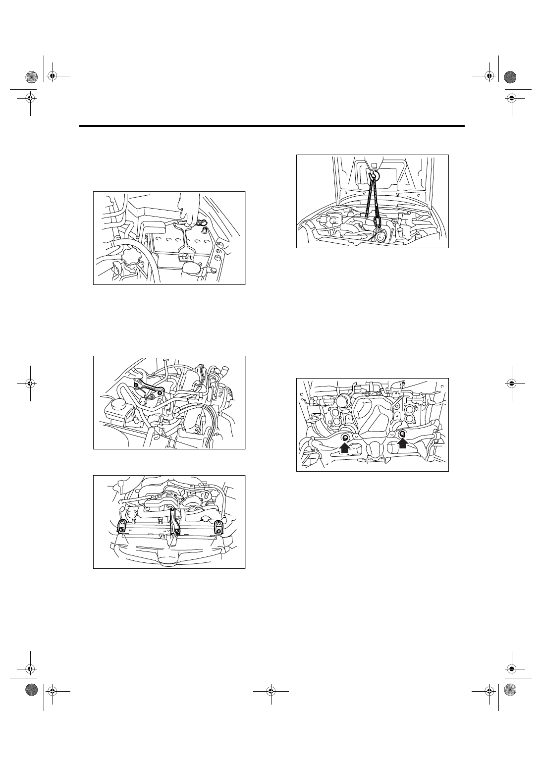
A: REMOVAL
1) Set the vehicle on a lift.
2) Remove the front wheels.
3) Disconnect the ground cable from battery.
4) Remove the air intake duct and air cleaner case.
<Ref. to IN(H4SO 2.0)-8, REMOVAL, Air Intake
Duct.> <Ref. to IN(H4SO 2.0)-5, REMOVAL, Air
Cleaner Case.>
5) Remove the air intake chamber. <Ref. to
IN(H4SO 2.0)-7, REMOVAL, Air Intake Chamber.>
6) Remove the pitching stopper.
7) Remove the hood stay holder (A) and radiator
upper brackets (B).
8) Support the engine with a lifting device and wire
ropes.
9) Lift-up the vehicle.
CAUTION:
When lifting up the vehicle, raise up wire ropes
at the same time.
10) Remove the under cover.
11) Drain the engine oil. <Ref. to LU(H4SO 2.0)-9,
REPLACEMENT, Engine Oil.>
12) Remove the front and center exhaust pipe.
<Ref. to EX(H4SO 2.0)-6, REMOVAL, Front Ex-
haust Pipe.> <Ref. to EX(H4SO 2.0)-9, REMOVAL,
Center Exhaust Pipe.>
13) Remove the nuts which install front cushion
rubber onto front crossmember.
14) Remove the bolts which install oil pan on cylin-
der block with engine raised up.
15) Insert the oil pan cutter blade into the clearance
between cylinder block and oil pan.
CAUTION:
Do not use a screwdriver or similar tool in place
of oil pan cutter.
16) Remove the oil strainer.
IN-00203
LU-00231
LU-00232
(A)
(B)
(B)
LU-00222
LU-00223
LU(H4SO 2.0)-16
LUBRICATION
Oil Pan and Strainer
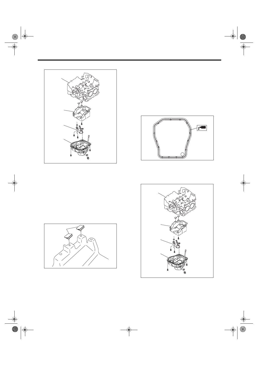
17) Remove the baffle plate.
B: INSTALLATION
CAUTION:
Before installing the oil pan, clean the mating
surface of oil pan and cylinder block.
1) Make sure that the seal (A) is installed securely
on the buffle plate in a direction as shown in the fig-
ure below.
2) Install the baffle plate.
Tightening torque:
6.4 N
⋅
m (0.65 kgf-m, 4.7 ft-lb)
3) Install the oil strainer onto baffle plate.
NOTE:
Replace the O-ring with a new one.
Tightening torque:
10 N
⋅
m (1.0 kgf-m, 7.2 ft-lb)
4) Apply liquid gasket to mating surfaces and install
the oil pan.
Liquid gasket:
THREE BOND 1207C (Part No. 004403012) or
equivalent
5) Tighten the bolt which installs oil pan to engine
block.
Tightening torque:
5 N
⋅
m (0.5 kgf-m, 3.7 ft-lb)
(A) Oil pan
(B) Oil strainer
(C) Baffle plate
(D) Cylinder block
LU-02156
(A)
(C)
(D)
(B)
LU-00052
(A)
(A) Oil pan
(B) Oil strainer
(C) Baffle plate
(D) Cylinder block
LU-00034
LU-02156
(A)
(C)
(D)
(B)
Нет комментариевНе стесняйтесь поделиться с нами вашим ценным мнением.
Текст