Subaru Legacy (2005 year). Service manual — part 672
6MT-35
MANUAL TRANSMISSION AND DIFFERENTIAL
Manual Transmission Assembly
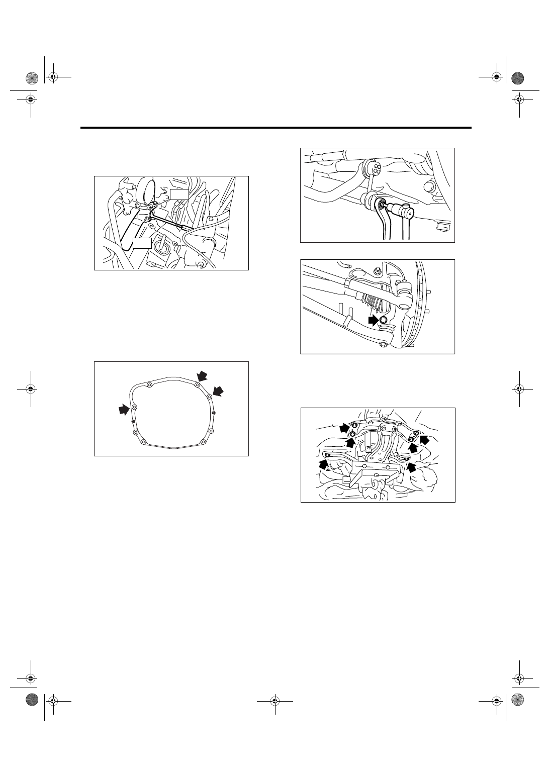
14) Set the ST.
ST1
41099AA010 ENGINE SUPPORT BRACK-
ET
ST2
41099AA020 ENGINE SUPPORT
15) Remove the clutch release shaft.
(1) Remove the plug with hexagon wrench.
(2) Install a 6 mm (0.24 in) bolt to the release
shaft, then pull out the release shaft.
(3) Lift up the release fork, and then remove it
from the release bearing claw. Pull release fork
to the engine side and set it free.
16) Remove the bolts which hold upper side of
transmission to engine.
17) Remove the front exhaust pipe, rear exhaust
pipe and muffler. <Ref. to EX(H6DO)-4, REMOV-
AL, Front Exhaust Pipe.> <Ref. to EX(H6DO)-7,
REMOVAL, Rear Exhaust Pipe.> <Ref. to
EX(H6DO)-9, REMOVAL, Muffler.>
CAUTION:
When removing the exhaust pipes, be careful
each exhaust pipe does not drop out.
18) Remove the heat shield cover.
19) Remove the propeller shaft. <Ref. to DS-10,
REMOVAL, Propeller Shaft.>
20) Remove the front stabilizer link.
21) Remove the ball joint of front arm from housing.
22) Remove the front drive shaft. <Ref. to DS-22,
REMOVAL, Front Drive Shaft.>
23) Set the transmission jack under the transmis-
sion, then remove the front crossmember and rear
crossmember.
MT-01269
ST2
ST1
MT-00466
FS-00117
FS-00106
MT-01264
6MT-36
MANUAL TRANSMISSION AND DIFFERENTIAL
Manual Transmission Assembly
24) Move the transmission to the right side of vehi-
cle, then remove the joint COMPL, stay bolt and re-
verse check cable.
NOTE:
If the transmission is not moved, joint COMPL and
stay bolt may contact the body. It will cause dam-
age.
25) Remove the fixing bolt of engine and transmis-
sion, then remove the transmission from vehicle.
NOTE:
• To facilitate removal, rotate the turn buckle of ST
(engine support) to lower the rear side of engine.
• Take care not to let the transmission contact with
body when pulling it backward to remove.
• Carefully remove the clutch pipe and breather
pipe because they may interfere each other.
B: INSTALLATION
1) Set the release fork, release bearing and release
shaft to transmission. <Ref. to CL-23, INSTALLA-
TION, Release Bearing and Lever.>
2) Install the transmission.
NOTE:
• Make sure the main shaft spline part is inserted
completely.
• Make sure the rear side of engine is lowered.
Tightening torque:
50 N
⋅
m (5.1 kgf-m, 36.9 ft-lb)
3) Move the transmission to the right side, then in-
stall the joint COMPL bolt, stay bolt and reverse
check cable.
Tightening torque:
T1: 11.8 N
⋅
m (1.2 kgf-m, 8.7 ft-lb)
T2: 32 N
⋅
m (3.3 kgf-m, 23.6 ft-lb)
(A) Joint COMPL bolt
(B) Stay bolt
(C) Reverse check cable
(C)
(A)
(B)
MT-00886
MT-01090
MT-00463
(A) Reverse check cable
MT-00464
MT-00465
(A)
T2
T1
6MT-37
MANUAL TRANSMISSION AND DIFFERENTIAL
Manual Transmission Assembly
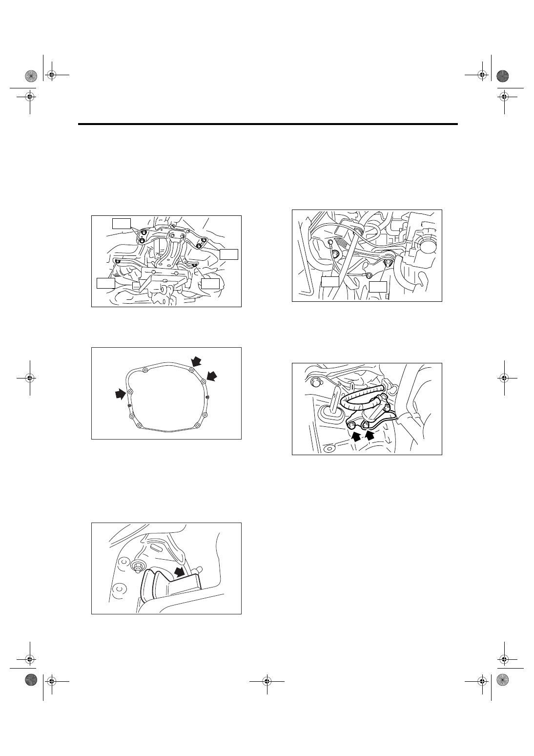
4) Install the front crossmember and rear cross-
member.
NOTE:
To facilitate installation, rotate the turn buckle of ST
(engine support) to lift up the rear side of engine.
Tightening torque:
T1: 70 N
⋅
m (7.1 kgf-m, 51.6 ft-lb)
T2: 140 N
⋅
m (14.3 kgf-m, 103 ft-lb)
5) Lower the vehicle and install the fixing bolt.
Tightening torque:
50 N
⋅
m (5.1 kgf-m, 36.9 ft-lb)
6) Make sure the release bearing is installed com-
pletely.
NOTE:
• Push the release fork to operating cylinder side
until you hear a “click” sound. Pull the release fork
to engine side. Setting is completed if the release
fork does not contact case.
• Make sure the boot cover is firmly set.
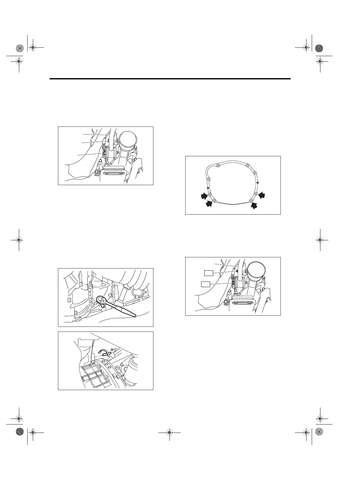
7) Install the pitching stopper bracket.
Tightening torque:
41 N
⋅
m (4.2 kgf-m, 30.2 ft-lb)
8) Install the pitching stopper.
Tightening torque:
T1: 50 N
⋅
m (5.1 kgf-m, 36.9 ft-lb)
T2: 58 N
⋅
m (5.9 kgf-m, 42.8 ft-lb)
9) Install the clutch operating cylinder.
Tightening torque:
41 N
⋅
m (4.2 kgf-m, 30.2 ft-lb)
NOTE:
Check that the clutch hose is routed properly.
10) Install the starter assembly. <Ref. to SC(H4SO
2.0)-6, INSTALLATION, Starter.>
MT-01265
T1
T2
T2
T1
MT-00466
MT-00467
MT-01281
T1
T2
MT-01268
6MT-38
MANUAL TRANSMISSION AND DIFFERENTIAL
Manual Transmission Assembly
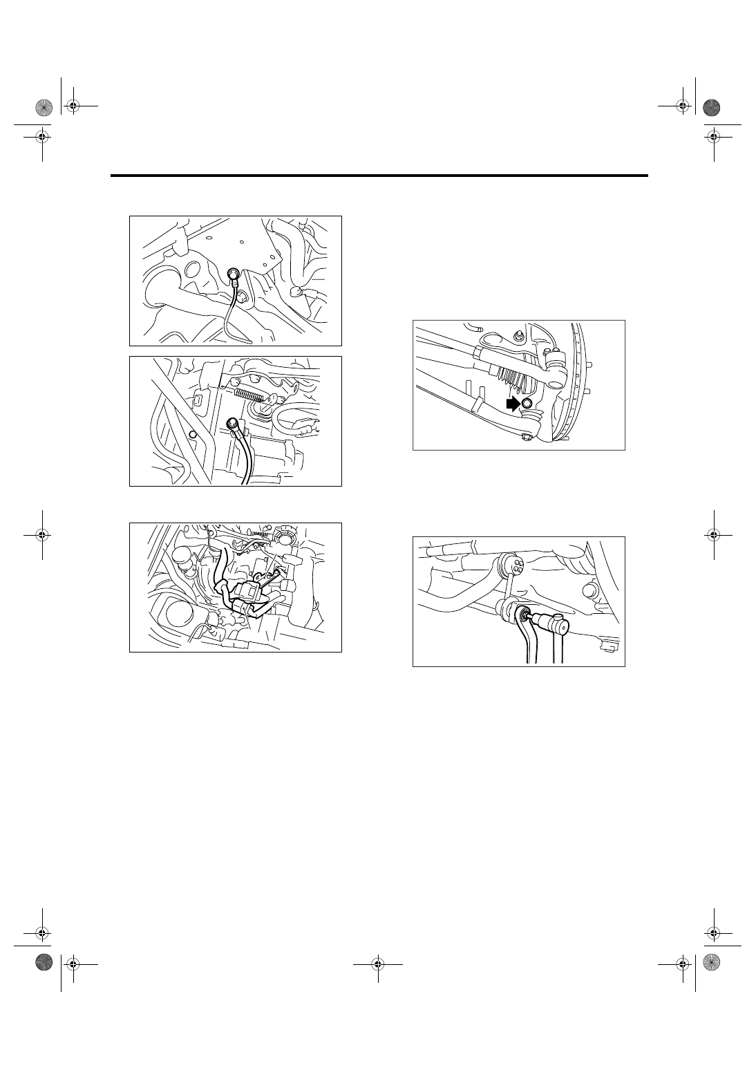
11) Install the ground cable to transmission and
body.
12) Connect the engine harness connectors, and
then install the engine hanger rear.
13) Replace the front differential side retainer oil
seal.
(1) Remove the oil seal by using flat tip screw-
driver, etc.
(2) Apply gear oil to the new oil seal lips.
(3) Install a new oil seal using the ST.
ST
18675AA000
DIFFERENTIAL SIDE OIL
SEAL INSTALLER
NOTE:
Always replace the differential side oil seal after ex-
tracting front drive shaft from the transmission.
14) Set the ST to side retainer.
ST
28399SA010
OIL SEAL PROTECTOR
15) Install the front drive shaft into transmission.
NOTE:
Replace the circlip of drive shaft with a new one.
16) Install the front drive shaft into transmission, re-
move the ST and insert the drive shaft securely.
ST
28399SA010
OIL SEAL PROTECTOR
17) Install the ball joint of front arm.
Tightening torque:
50 N
⋅
m (5.1 kgf-m, 36.9 ft-lb)
18) Install the front stabilizer link.
Tightening torque:
45 N
⋅
m (4.6 kgf-m, 33.2 ft-lb)
NOTE:
Use a new self-locking nut.
19) Install the heat shield cover.
20) Install the propeller shaft. <Ref. to DS-11, IN-
STALLATION, Propeller Shaft.>
21) Install the front exhaust pipe, rear exhaust pipe
and muffler. <Ref. to EX(H6DO)-5, INSTALLA-
TION, Front Exhaust Pipe.> <Ref. to EX(H6DO)-7,
INSTALLATION, Rear Exhaust Pipe.> <Ref. to
EX(H6DO)-9, INSTALLATION, Muffler.>
22) Install the universal joint. <Ref. to PS-22, IN-
STALLATION, Universal Joint.>
23) Install the under cover.
24) Pour transmission gear oil.
<Ref. to 6MT-29, REPLACEMENT, Transmission
Gear Oil.>
25) Install the air cleaner case. <Ref. to IN(H6DO)-
6, INSTALLATION, Air Cleaner Case.>
(A) Engine harness connectors
(B) Engine hanger rear
MT-01266
MT-01267
MT-01302
(B)
(A)
FS-00106
FS-00117
Нет комментариевНе стесняйтесь поделиться с нами вашим ценным мнением.
Текст