Subaru Legacy (2005 year). Service manual — part 1022
CC(diag)-25
CRUISE CONTROL SYSTEM (DIAGNOSTICS)
Diagnostic Procedure with Diagnostic Trouble Code (DTC)
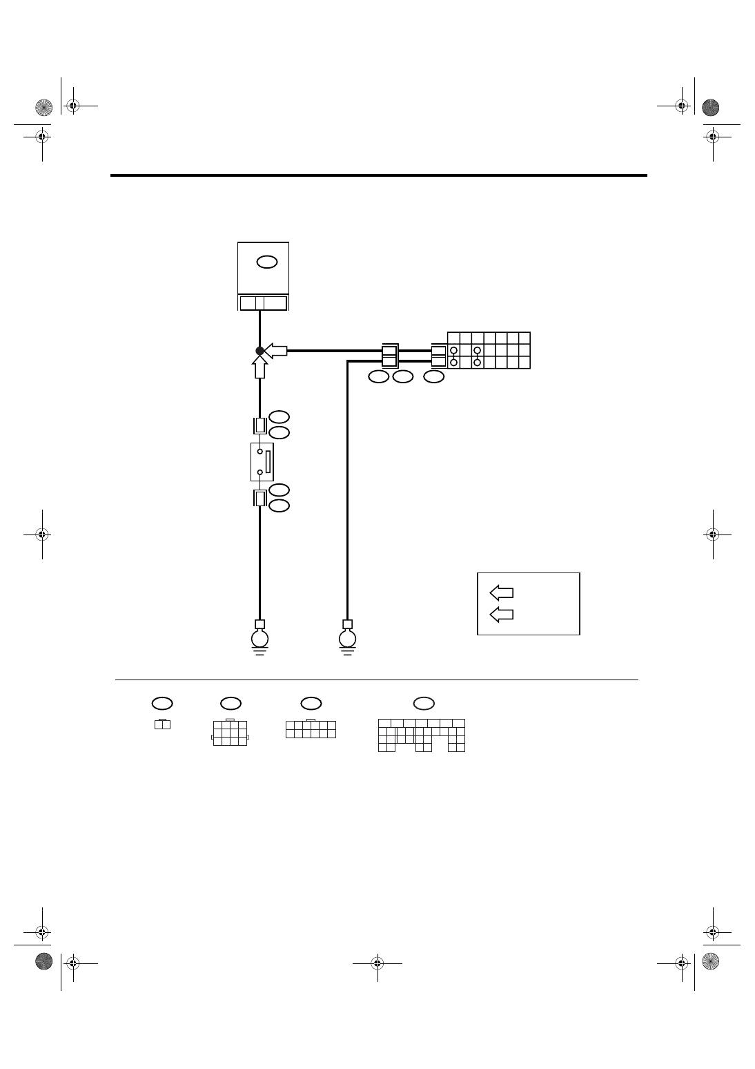
• 2.5 L EC, K4 and EK model
B25
T7
B12
E
E
T7
T3
B12
12
P
R
N
D
3
2
1
7
12
11
AT
MT
1 2 3 4
5 6 7 8
9 10 11 12
1 2 3 4 5 6
7 8 9 10 11 12
ECM
D9
INHIBITOR SWITCH
CC-00269
B25
T2
1
T2
B25
2
NEUTRAL
POSITION
SWITCH
B137
D:
1 2
B137
5
6
7
8
2
1
9
4
3
10
22 23
11 12 13 14 15
24 25
26
16 17
18 19 20 21
27
28 29
30 31
D:
: AT MODEL
: MT MODEL
AT
MT
CC(diag)-26
CRUISE CONTROL SYSTEM (DIAGNOSTICS)
Diagnostic Procedure with Diagnostic Trouble Code (DTC)
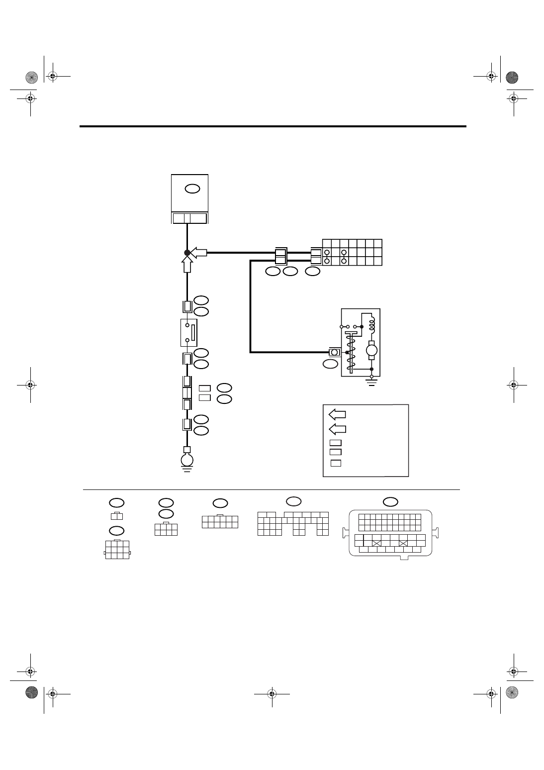
• 2.0 L non-turbo model, 2.5 L KS, KA model
B25
T7
B12
E
T7
T3
B12
7
P
R
N
D
3
2
1
12
11
12
AT
MT
1 2 3 4
5 6 7 8
9 10 11 12
1 2 3 4 5 6
7 8 9 10 11 12
ECM
B12
INHIBITOR SWITCH
CC-00270
B25
T2
2
T2
B25
1
NEUTRAL
POSITION
SWITCH
B135
B:
1 2
: LHD MODEL
: RHD MODEL
LHD
RHD
*
: TERMINAL No. RANDOM
ARRANGEMENT
M
B14
STARTER MOTOR
MT
: MT MODEL
AT
: AT MODEL
*
*
:
:
LHD
RHD
B83
B122
E2
B21
36
B135
5
6
7
8
2
1
9
4
3
10
24
22 23
25
11 12 13 14 15
26 27
28
16 17 18 19
20 21
29 30 31
32 33
34 35
B:
B21
1 2 3 4
12 13 14 15
5 6 7 8
16 17 18 19
9 10 11
20 21 22
23 24 25 26 27 28 29 30 31 32 33
35
34
37
36
39
38
41
40
43
42
44
45
47
46
49
48
51
50
53
52
54
B83
B122
1 2 3 4
5 6 7 8
CC(diag)-27
CRUISE CONTROL SYSTEM (DIAGNOSTICS)
Diagnostic Procedure with Diagnostic Trouble Code (DTC)
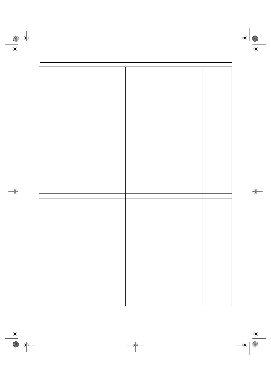
Step
Check
Yes
No
1
CHECK VEHICLE FOR SPECIFICATION.
Check the vehicle for destination and specifica-
tion.
Is the vehicle turbo model or
3.0 L model?
2
CHECK NEUTRAL POSITION SWITCH.
1) Connect the Subaru Select Monitor to data
link connector.
2) Turn the ignition switch and Subaru Select
Monitor switch to ON.
3) Select {Engine} from the main menu.
4) Then, select {Current Data Display &
Save}.
5) Check the neutral position switch signal by
shifting the select lever to “P” or “N” range.
Is ON displayed in the Subaru
Select Monitor when the select
lever is in “P” or “N” range?
Or is OFF displayed in the
Subaru Select Monitor when
the select lever is in other than
“P” or “N” range?
Replace the ECM.
<Ref. to
FU(H4DOTC)-34,
Engine Control
Module (ECM).>
<Ref. to
FU(H6DO)-34,
Engine Control
Module (ECM).>
3
CHECK TCM OUTPUT VOLTAGE.
1) Turn the ignition switch to ON.
2) Measure the voltage between TCM har-
ness connector terminal and chassis ground.
Connector & terminal
(B55) No. 19 (+) — Chassis ground (
−
):
Is the voltage more than 10 V
when the select lever is in
other than “P” or “N” range?
Or is the voltage less than 1 V
when the select lever is in “P”
or “N” range?
Inspect the TCM.
<Ref. to 5AT(diag)-
2, Basic Diagnos-
tic Procedure.>
4
CHECK HARNESS BETWEEN TCM AND
ECM.
1) Turn the ignition switch to OFF.
2) Disconnect the harness connector from
TCM and ECM.
3) Measure the resistance between TCM har-
ness connector terminal and ECM harness
connector terminal.
Connector & terminal
(B137) No. 9 — (B55) No. 19:
Is the resistance less than 10
Ω?
Replace the ECM.
<Ref. to
FU(H4DOTC)-34,
Engine Control
Module (ECM).>
<Ref. to
FU(H6DO)-34,
Engine Control
Module (ECM).>
Repair the wiring
harness.
5
CHECK TRANSMISSION TYPE.
Is the transmission type AT?
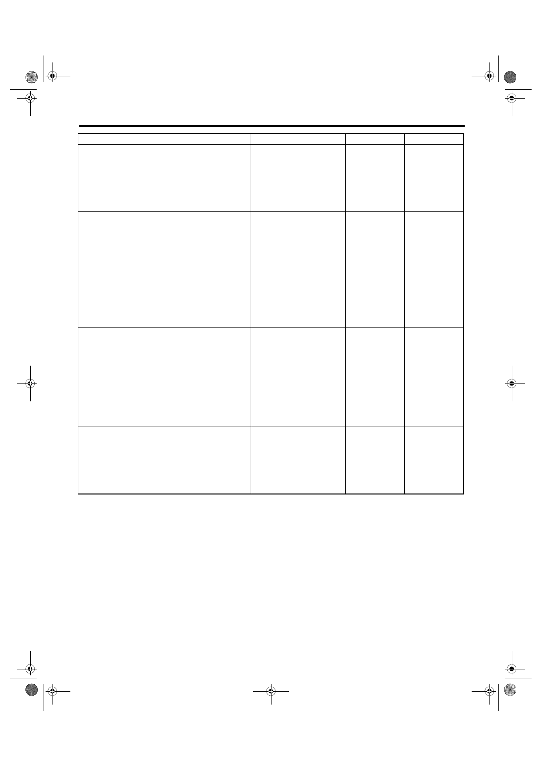
6
CHECK INHIBITOR SWITCH CIRCUIT.
1) Turn the ignition switch to OFF.
2) Disconnect the inhibitor switch harness
connector.
3) Turn the ignition switch to ON.
4) Measure the voltage between harness con-
nector terminal and chassis ground.
Connector & terminal
2.5 L EC, K4 and EK model:
(T7) No. 12 (+) — Chassis ground (
−
):
2.0 L non-turbo model, 2.5 L KS, KA
model:
(T7) No. 7 (+) — Chassis ground (
−
):
Is the voltage approx. 5 V?
Check the harness
for open or short
between inhibitor
switch and ECM.
7
CHECK INHIBITOR SWITCH CIRCUIT.
1) Turn the ignition switch to OFF.
2) Disconnect the starter motor harness con-
nector.
3) Measure the resistance between inhibitor
switch harness connector terminal and chassis
ground.
Connector & terminal
2.5 L EC, K4 and EK model:
(T7) No. 7 — Chassis ground:
2.0 L non-turbo model, 2.5 L KS, KA
model:
(T7) No. 12 — Chassis ground:
Is the resistance less than 10
Ω?
Repair the har-
ness.
CC(diag)-28
CRUISE CONTROL SYSTEM (DIAGNOSTICS)
Diagnostic Procedure with Diagnostic Trouble Code (DTC)
8
CHECK INHIBITOR SWITCH.
Remove and check the inhibitor switch. <Ref.
to CC-8, Inhibitor Switch.>
Is the inhibitor switch OK?
Replace the ECM.
<Ref. to FU(H4SO
2.0)-34, Engine
Control Module
(ECM).> <Ref. to
FU(H4SO 2.5)-37,
Engine Control
Module (ECM).>
Replace the inhibi-
tor switch.
9
CHECK NEUTRAL POSITION SWITCH CIR-
CUIT.
1) Turn the ignition switch to OFF.
2) Disconnect the neutral position switch har-
ness connector.
3) Turn the ignition switch to ON.
4) Measure the voltage between harness con-
nector terminal and chassis ground.
Connector & terminal
2.5 L EC, K4 and EK model:
(B25) No. 1 (+) — Chassis ground (
−
):
2.0 L non-turbo model, 2.5 L KS, KA
model:
(B25) No. 2 (+) — Chassis ground (
−
):
Is the voltage approx. 5 V?
Check the harness
for open or short
between neutral
position switch and
ECM.
10
CHECK NEUTRAL POSITION SWITCH CIR-
CUIT.
1) Turn the ignition switch to OFF.
2) Measure the resistance between neutral
position switch harness connector terminal and
chassis ground.
Connector & terminal
2.5 L EC, K4 and EK model:
(B25) No. 2 — Chassis ground:
2.0 L non-turbo model, 2.5 L KS, KA
model:
(B25) No. 1 — Chassis ground:
Is the resistance less than 10
Ω?
Repair the har-
ness.
11
CHECK NEUTRAL POSITION SWITCH.
Remove and check the neutral position switch.
<Ref. to CC-9, Neutral Position Switch.>
Is the neutral position switch
OK?
Replace the ECM.
<Ref. to FU(H4SO
2.0)-34, Engine
Control Module
(ECM).> <Ref. to
FU(H4SO 2.5)-37,
Engine Control
Module (ECM).>
Replace the neu-
tral position switch.
Step
Check
Yes
No
Нет комментариевНе стесняйтесь поделиться с нами вашим ценным мнением.
Текст