Subaru Legacy (2005 year). Service manual — part 1020
CC(diag)-17
CRUISE CONTROL SYSTEM (DIAGNOSTICS)
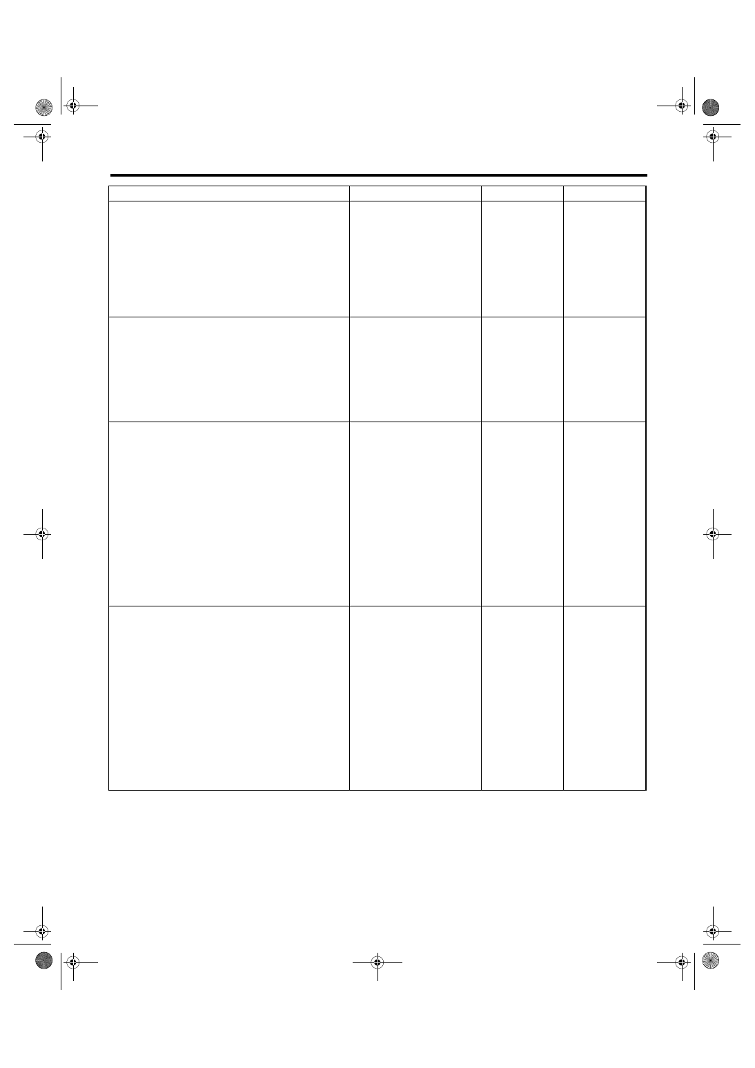
Diagnostic Procedure with Diagnostic Trouble Code (DTC)
Step
Check
Yes
No
1
CHECK CRUISE CONTROL COMMAND
SWITCH.
1) Remove the driver’s airbag module. <Ref.
to AB-16, REMOVAL, Driver’s Airbag Module.>
2) Disconnect the harness connector of cruise
control command switch.
3) Turn the ignition switch to ON.
4) Measure the voltage between harness con-
nector terminal and chassis ground.
Connector & terminal
(ST3) No. 1 (+) — Chassis ground (
−
):
(ST3) No. 3 (+) — Chassis ground (
−
):
Is the voltage more than 5 V?
Check the harness
for open or short
circuit between
cruise control
command switch
and ECM.
2
INSPECTION FOR CANCEL SWITCH.
1) Turn the ignition switch to OFF.
2) Remove the cruise control command
switch. <Ref. to CC-5, REMOVAL, Cruise Con-
trol Command Switch.>
3) Measure the resistance between switch ter-
minals when CANCEL switch is pressed and
not pressed.
Terminals
No. 2 — No. 3:
Is the resistance less than 1
Ω
when CANCEL switch is
pressed? Is the resistance
approx. 4 k
Ω when CANCEL
switch is not pressed?
Replace the cruise
control command
switch. <Ref. to
CC-5, Cruise Con-
trol Command
Switch.>
3
CHECK SET/COAST SWITCH.
Measure the resistance between switch termi-
nals when SET/COAST switch is pressed and
not pressed.
Terminals
No. 2 — No. 3:
Is the resistance approx. 250
Ω
when SET/COAST switch is
pressed? Is the resistance
approx. 4 k
Ω when SET/
COAST switch is not pressed?
Replace the cruise
control command
switch. <Ref. to
CC-5, Cruise Con-
trol Command
Switch.>
4
CHECK RESUME/ACCEL SWITCH CIRCUIT.
Measure the resistance between switch termi-
nals when RESUME/ACCEL switch is pressed
and not pressed.
Terminals
No. 2 — No. 3:
Is the resistance approx. 1500
Ω when RESUME/ACCEL
switch is pressed? Is the resis-
tance approx. 4 k
Ω when
RESUME/ACCEL switch is not
pressed?
Replace the cruise
control command
switch. <Ref. to
CC-5, Cruise Con-
trol Command
Switch.>
CC(diag)-18
CRUISE CONTROL SYSTEM (DIAGNOSTICS)
Diagnostic Procedure with Diagnostic Trouble Code (DTC)
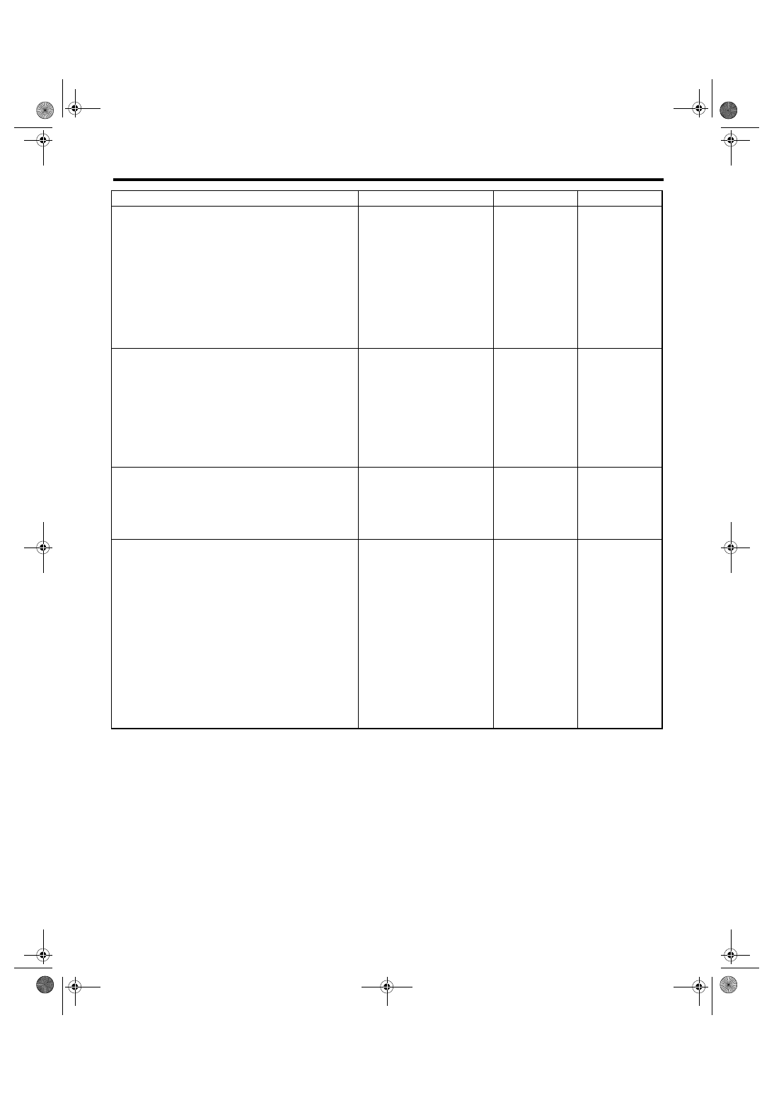
B: DTC 12 AND 25 STOP LIGHT SWITCH AND BRAKE SWITCH
TROUBLE SYMPTOM:
• Cruise control cannot be set.
• Cruise control cannot be released.
WIRING DIAGRAM:
• 2.0 L turbo model, 3.0 L model, 2.5 L EC, K4 and EK model
CC-00362
B65
MAIN SBF
SBF-2
F/B No.8
B65
4
3
1
2
C8
C10
C9
1 2
3 4
B136
C:
B136
9
30
29
28
32
31
20
19
18
22
21
10
12
11
14
24
34
33
27
26
16
1
2
3
4
5
6
13
23
15
25
8
7
17
35
C:
SBF-8
F/B No.4
F5
B159
F9
F:
9
4
7
6
2
1
5
3
8
B159
F:
ECM
BATTERY
STOP LIGHT SWITCH
AND BRAKE SWITCH
BRAKE
SWITCH
STOP LIGHT
SWITCH
IGNITION
RELAY
FUSE & RELAY BOX
CLUTCH SWITCH (MT)
2
1
B107
MT
MT
1 2
B107
CC(diag)-19
CRUISE CONTROL SYSTEM (DIAGNOSTICS)
Diagnostic Procedure with Diagnostic Trouble Code (DTC)
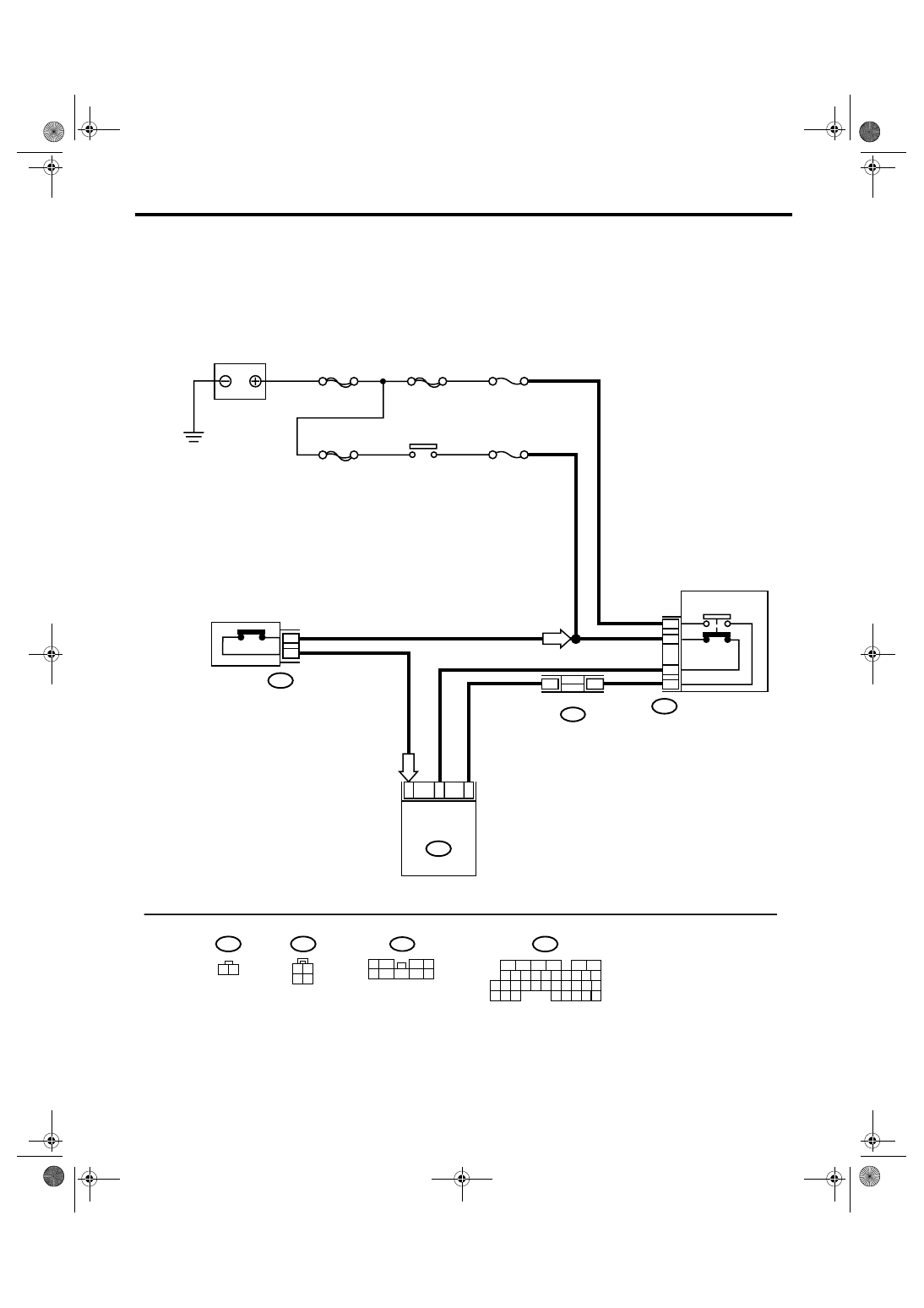
• 2.0 L non-turbo model, 2.5 L for KS, KA model
CC-00363
B65
MAIN SBF
SBF-2
F/B No.8
B65
4
3
1
2
D13
D22
D12
1 2
3 4
B137
D:
SBF-8
F/B No.4
F5
B159
F9
F:
9
4
7
6
2
1
5
3
8
B159
F:
ECM
BATTERY
STOP LIGHT SWITCH
AND BRAKE SWITCH
BRAKE
SWITCH
STOP LIGHT
SWITCH
IGNITION
RELAY
FUSE & RELAY BOX
CLUTCH SWITCH (MT)
2
1
B107
MT
MT
1 2
B107
B137
5
6
7
8
2
1
9
4
3
10
22 23
11 12 13 14 15
24 25
26
16 17
18 19 20 21
27
28 29
30 31
D:
CC(diag)-20
CRUISE CONTROL SYSTEM (DIAGNOSTICS)
Diagnostic Procedure with Diagnostic Trouble Code (DTC)
Step
Check
Yes
No
1
CHECK STOP LIGHT SWITCH AND BRAKE
SWITCH CIRCUIT.
1) Turn the ignition switch to OFF.
2) Disconnect the stop light switch and brake
switch harness connector.
3) Turn the ignition switch to ON.
4) Measure the voltage between harness con-
nector terminal and chassis ground.
Connector & terminal
(B65) No. 2 (+) — Chassis ground (
−
):
Is the voltage more than 10 V? Go to step 2.
• Check fuse No.
8 (in fuse & relay
box).
• Check the har-
ness for open or
short between
stop light/brake
switch and fuse &
relay box.
2
CHECK STOP LIGHT SWITCH AND BRAKE
SWITCH CIRCUIT.
Measure the voltage between harness connec-
tor terminal and chassis ground.
Connector & terminal
(B65) No. 4 (+) — Chassis ground (
−
):
Is the voltage more than 10 V? Go to step 3.
• Check fuse No.
4 (in fuse & relay
box).
• Check the har-
ness for open or
short between
stop light/brake
switch and fuse &
relay box.
3
CHECK STOP LIGHT SWITCH AND BRAKE
SWITCH CIRCUIT.
1) Turn the ignition switch to OFF.
2) Disconnect the harness connector of ECM.
3) Measure the resistance between ECM har-
ness connector terminal and stop light switch
and brake switch harness connector terminal.
Connector & terminal
2.0 L turbo model, 3.0 L model, 2.5 L EC,
K4 and EK model:
(B136) No. 8 — (B65) No. 3:
(B136) No. 9 — (B65) No. 1:
2.0 L non-turbo model, 2.5 L KS, KA
model:
(B137) No. 13 — (B65) No. 3:
(B137) No. 12 — (B65) No. 1:
Is the resistance less than 10
Ω?
Repair the har-
ness.
4
CHECK STOP LIGHT SWITCH AND BRAKE
SWITCH.
Remove and check the stop light switch and
brake switch. <Ref. to CC-6, Stop Light &
Brake Switch.>
Are the stop light switch and
brake switch OK?
Replace the stop
light switch and
brake switch.
Нет комментариевНе стесняйтесь поделиться с нами вашим ценным мнением.
Текст