Subaru Legacy (2005 year). Service manual — part 599
5AT-95
AUTOMATIC TRANSMISSION
Front Differential Assembly
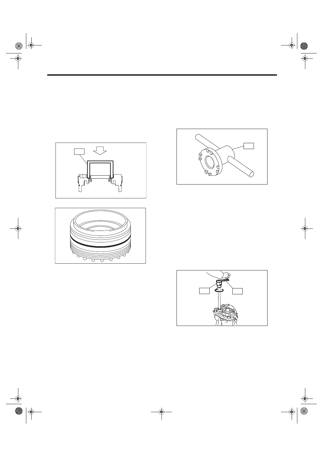
2. SIDE RETAINER
NOTE:
Install the oil seal and O-ring of side retainer after
the adjustment of backlash and tooth contact.
1) Install the bearing outer race to side retainer.
2) Install a new oil seal using ST.
ST
18675AA000
DIFFERENTIAL SIDE OIL
SEAL INSTALLER
NOTE:
Apply oil to the oil seal lips.
3) Install a new O-ring.
E: INSPECTION
• Check each component for scratches, damage
or other faults.
• Measure the backlash, and then adjust it within
specification.
<Ref. to 5AT-95, ADJUSTMENT, Front Differential
Assembly.>
F: ADJUSTMENT
1) Using the ST, screw-in the retainer until resis-
tance is felt.
NOTE:
Screw-in the RH side slightly deeper than the LH
side.
ST
18630AA010
WRENCH COMPL RETAIN-
ER
2) Remove the oil pump cover.
3) Remove the liquid gasket from the mating sur-
face completely.
4) Install the oil pump cover to converter case, and
secure them with tightening four bolts evenly.
NOTE:
Use an old gasket or aluminum washer so as not to
damage the mating surface of housing.
Tightening torque:
41 N
⋅
m (4.2 kgf-m, 30.2 ft-lb)
5) Rotate the drive pinion ten times or more using
ST1 and ST2.
ST1
18667AA010 HOLDER
ST2
499787700
WRENCH
AT-00226
ST
AT-00219
AT-00227
ST
AT-01985
ST2
ST1
5AT-96
AUTOMATIC TRANSMISSION
Front Differential Assembly
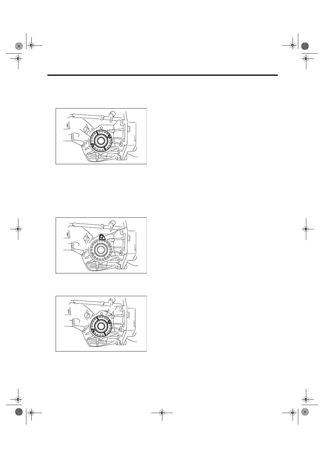
6) Tighten the retainer LH by rotating the shaft until
resistance is felt. Then loosen the retainer RH.
Keep tightening the retainer LH, and loosening the
retainer RH until the pinion shaft no longer be
turned. This is to the “zero” state.
7) After the “zero” state is established, back off the
retainer LH three notches and secure it with the
lock plate (A). Then back off the retainer RH and re-
tighten until it stops. Rotate the drive pinion two to
three times. Tighten the retainer RH further 1-3/4
notches. This sets the preload. Finally, secure the
retainer with its lock plate.
NOTE:
Turning the retainer by one tooth changes the
backlash approx. 0.05 mm (0.0020 in).
8) Turn the drive pinion several times using ST1,
and check to see if the backlash is within the spec-
ification using ST2, ST3, ST4 and ST5.
ST1
499787700
WRENCH
ST2
498247001
MAGNET BASE
ST3
498247100
DIAL GAUGE
ST4
499787500
ADAPTER
ST5
498255400
PLATE
Backlash:
0.13 — 0.18 mm (0.0051 — 0.0071 in)
9) Adjust the tooth contact between front differen-
tial and drive shaft. <Ref. to 5AT-89, ADJUST-
MENT, Drive Pinion Shaft Assembly.>
(A) Retainer
(A) 0.05 mm (0.0020 in)
AT-01986
(A)
AT-01988
(A)
AT-01989
(A)
5AT-97
AUTOMATIC TRANSMISSION
AT Main Case
35.AT Main Case
A: REMOVAL
1) Remove the transmission assembly from vehi-
cle. <Ref. to 5AT-38, REMOVAL, Automatic Trans-
mission Assembly.>
2) Pull out the torque converter assembly. <Ref. to
5AT-70, REMOVAL, Torque Converter Assembly.>
3) Remove the transmission harness connector
from stay.
4) Disconnect the air breather hose.
5) Remove the oil charge pipe. <Ref. to 5AT-69,
REMOVAL, Oil Charge Pipe.>
6) Remove the ATF filter inlet and outlet pipes.
<Ref. to 5AT-60, REMOVAL, ATF Filter.>
7) Remove the extension case and intermediate
case. <Ref. to 5AT-71, REMOVAL, Extension
Case and Intermediate Case.>
8) Remove the center differential carrier. <Ref. to
5AT-78, REMOVAL, Center Differential Carrier.>
9) Remove the reduction driven gear. <Ref. to 5AT-
76, REMOVAL, Reduction Driven Gear.>
10) Separate the converter case and transmission
case. <Ref. to 5AT-82, REMOVAL, Converter
Case.>
11) Remove the control valve body. <Ref. to 5AT-
58, REMOVAL, Control Valve Body.>
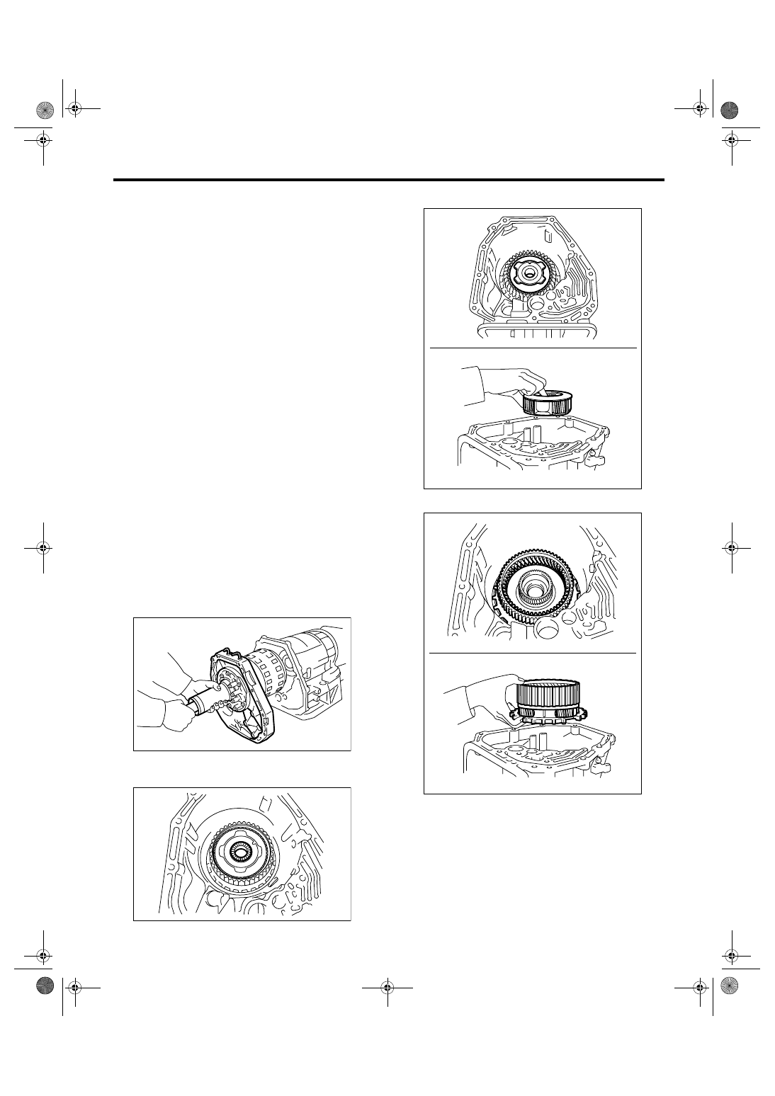
12) Remove the oil pump cover.
<Ref. to 5AT-84, REMOVAL, Oil Pump Cover.>
NOTE:
The input clutch pack assembly and front sun gear
assembly are also removed together.
13) Remove the needle bearing of middle carrier
assembly.
14) Remove the middle carrier assembly.
15) Remove the rear carrier assembly.
AT-01990
AT-01991
AT-01992
AT-01993
5AT-98
AUTOMATIC TRANSMISSION
AT Main Case
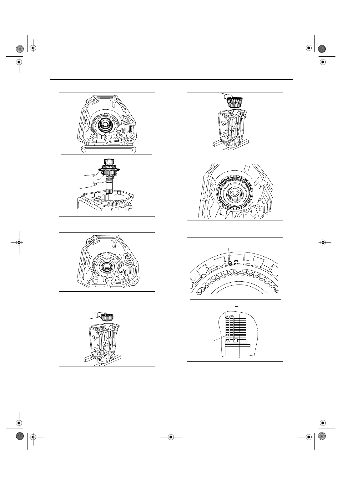
16) Remove the middle & rear sun gear assembly.
17) Remove the thrust needle bearing of high & low
reverse clutch.
18) Remove the high & low reverse clutch assem-
bly.
19) Remove the direct clutch assembly.
20) Remove the snap ring of reverse brake.
21) Remove the retaining plate.
22) Remove the leaf spring.
23) Take out the drive plate, driven plate and dish
plate.
AT-01994
AT-01995
AT-01996
(A) Leaf spring
AT-01997
AT-01998
AT-01999
(A)
B’
B
(A)
B’
B
Нет комментариевНе стесняйтесь поделиться с нами вашим ценным мнением.
Текст