Subaru Legacy (2005 year). Service manual — part 597
5AT-87
AUTOMATIC TRANSMISSION
Drive Pinion Shaft Assembly
33.Drive Pinion Shaft Assembly
A: REMOVAL
1) Remove the transmission assembly from vehi-
cle. <Ref. to 5AT-38, REMOVAL, Automatic Trans-
mission Assembly.>
2) Pull out the torque converter assembly. <Ref. to
5AT-70, REMOVAL, Torque Converter Assembly.>
3) Remove the transmission harness connector
from stay.
4) Disconnect the air breather hose. <Ref. to 5AT-
68, REMOVAL, Air Breather Hose.>
5) Remove the oil charge pipe. <Ref. to 5AT-69,
REMOVAL, Oil Charge Pipe.>
6) Remove the ATF filter inlet and outlet pipes.
<Ref. to 5AT-60, REMOVAL, ATF Filter.>
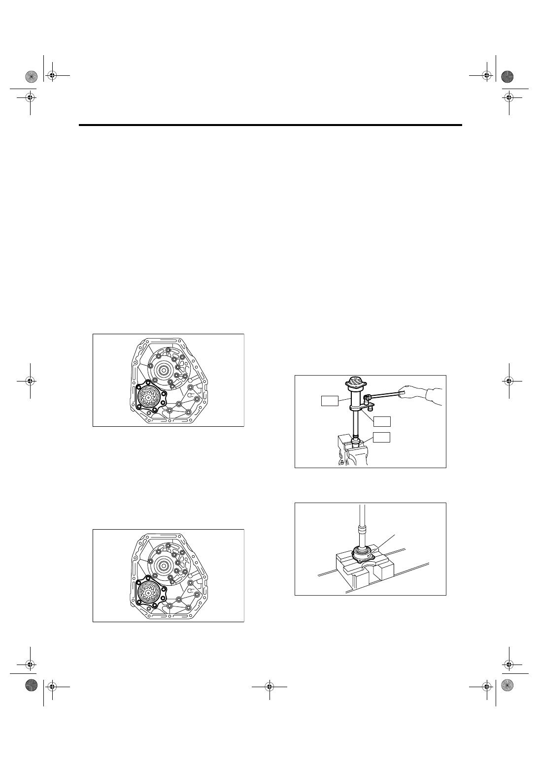
7) Separate the converter case and transmission
case part. <Ref. to 5AT-82, REMOVAL, Converter
Case.>
8) Remove the drive pinion shaft mounting bolt,
and then remove the drive pinion shaft assembly
from oil pump cover.
9) Remove the oil pump cover from AT main case.
<Ref. to 5AT-84, REMOVAL, Oil Pump Cover.>
B: INSTALLATION
1) Assemble the drive pinion assembly to oil pump
cover.
NOTE:
Be careful not to bend the shim.
Tightening torque:
70 N
⋅
m (7.1 kgf-m, 51.6 ft-lb)
2) Adjust the tooth contact between drive pinion
shaft assembly and front differential side gear.
<Ref. to 5AT-89, ADJUSTMENT, Drive Pinion
Shaft Assembly.>
3) Combine the converter case with transmission
case. <Ref. to 5AT-82, INSTALLATION, Converter
Case.>
4) Install the transmission harness connector to the
stay.
5) Install the ATF filter pipe. <Ref. to 5AT-60, IN-
STALLATION, ATF Filter.>
6) Install the oil charge pipe with O-ring.
7) Install the torque converter assembly. <Ref. to
5AT-70, INSTALLATION, Torque Converter As-
sembly.>
8) Install the transmission assembly into vehicle.
<Ref. to 5AT-42, INSTALLATION, Automatic
Transmission Assembly.>
C: DISASSEMBLY
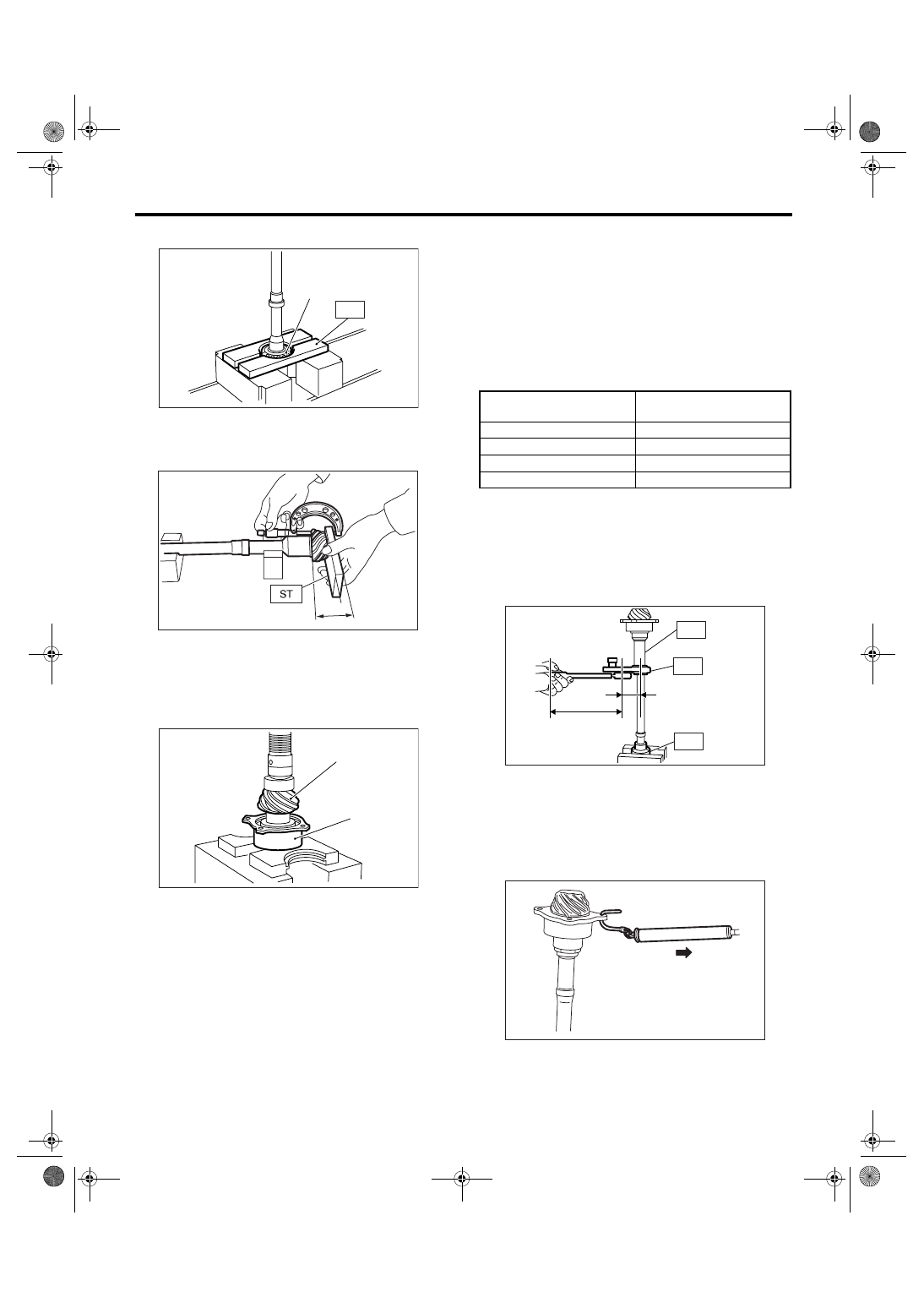
1) Remove the caulking part of lock nut, and then
remove the lock nut with holding rear spline part of
the shaft using ST1 and ST2. Pull out the drive pin-
ion collar.
ST1
18667AA010 HOLDER
ST2
499787700
WRENCH
ST3
499787500
ADAPTER
2) Remove the O-ring.
3) Separate the rear roller bearing and outer race
(A) from shaft using press.
4) Separate the front roller bearing (A) from shaft
using press and ST.
AT-01984
AT-01984
AT-00197
ST1
ST3
ST2
AT-00198
(A)
5AT-88
AUTOMATIC TRANSMISSION
Drive Pinion Shaft Assembly
ST
498517000
REPLACER
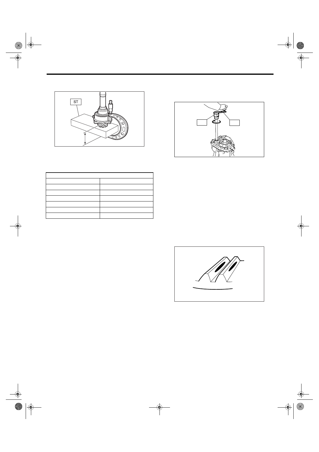
D: ASSEMBLY
1) Measure the dimension “A” of drive pinion shaft.
ST
398643600
GAUGE
2) Using a press, press-fit the new roller bearing
into specified position.
NOTE:
If excessive force is applied to roller bearing, the
roller bearing will not turn easily.
3) After fitting a new O-ring to the shaft, attach the
drive pinion collar to shaft.
4) Install the lock washer to drive pinion shaft in
proper direction.
5) Tighten new lock nuts using ST1, ST2 and ST3.
Calculate the lock washer and lock nut specifica-
tion using following formula.
T2 = L2/(L1 + L2)
× T1
T1: 116 N
⋅m (11.8 kgf-m, 85.3 ft-lb)
[Required torque setting]
T2: Tightening torque
L1: ST2 length 0.072 m (2.83 in)
L2: Torque wrench length
Example:
ST1
18667AA010 HOLDER
ST2
499787700
WRENCH
ST3
499787500
ADAPTER
NOTE:
Install the ST2 to torque wrench as straight as pos-
sible.
6) Measure the starting torque of bearing. Make
sure the starting torque is within the specification. If
the torque is not within specification, replace the
roller bearing.
Starting torque:
7.6 — 38.1 N (0.776 — 3.88 kgf, 1.7 — 8.6 lbf)
7) Stake the caulking of lock nut at two points.
(A) Drive pinion shaft
(B) Roller bearing
AT-00199
(A)
ST
A
AT-00200
AT-00201
(B)
(A)
Torque wrench length
m (in)
Tightening torque
N
⋅m (kgf-m, ft-lb)
0.4 (15.75)
98 (10.0, 72)
0.45 (17.72)
100 (10.2, 73.8)
0.5 (19.69)
101 (10.3, 74.5)
0.55 (21.65)
102 (10.4, 75)
ST1
AT-00202
L1 [m (in)]
L2 [m (in)]
ST2
ST3
AT-00203
5AT-89
AUTOMATIC TRANSMISSION
Drive Pinion Shaft Assembly
8) Measure the dimension “B” of drive pinion shaft
ST
398643600
GAUGE
9) Calculate the thickness “t” (mm) of drive pinion
shim.
t = 6.5
± 0.0625 − (B − A)
10) Select three or less shims from following table.
E: INSPECTION
• Make sure that all component parts are free of
scratches, holes and other faults.
• Adjust the teeth alignment. <Ref. to 5AT-89, AD-
JUSTMENT, Drive Pinion Shaft Assembly.>
F: ADJUSTMENT
1) Remove the liquid gasket from the mating sur-
face completely.
2) Install the converter case to oil pump cover, and
secure them with tightening four bolts evenly.
NOTE:
Use an old gasket or aluminum washer so as not to
damage the mating surface of housing.
Tightening torque:
41 N
⋅
m (4.2 kgf-m, 30.2 ft-lb)
3) Rotate the drive pinion several times using ST1
and ST2.
ST1
18667AA010 HOLDER
ST2
499787700
WRENCH
4) Adjust the backlash between drive pinion and
hypoid driven gear. <Ref. to 5AT-95, ADJUST-
MENT, Front Differential Assembly.>
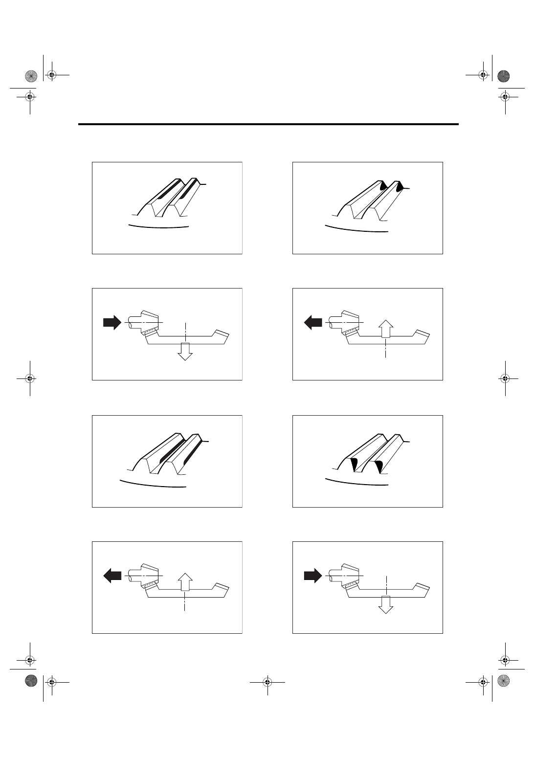
5) Apply red lead evenly to the surfaces of three or
four teeth on hypoid driven gear. Rotate the drive
pinion in the leftward and rightward for several
times. Remove the oil pump cover, and check the
tooth contact pattern.
If the tooth contact is improper, readjust the back-
lash or shim thickness. <Ref. to 5AT-95, ADJUST-
MENT, Front Differential Assembly.>
• Correct tooth contact
Checking item: Tooth contact pattern is slightly
shifted toward to toe side under no-load
rotation. (When loaded, it moves toward heel
side.)
Drive pinion shim
Part No.
Thickness mm (in)
31451AA180
0.150 (0.0059)
31451AA190
0.175 (0.0069)
31451AA200
0.200 (0.0079)
31451AA210
0.225 (0.0089)
31451AA220
0.250 (0.0098)
31451AA230
0.275 (0.0108)
B
AT-00204
(A) Toe side
(B) Heel side
AT-01985
ST2
ST1
AT-00207
(A)
(B)
5AT-90
AUTOMATIC TRANSMISSION
Drive Pinion Shaft Assembly
• Face contact
Checking item: Backlash is too large.
Contact pattern
Corrective action: Increase thickness of drive pin-
ion height adjusting washer in order to bring drive
pinion close to driven gear.
• Flank contact
Checking item: Backlash is too small.
Contact pattern
Corrective action: Reduce thickness of pinion
height adjusting washer in order to bring drive pin-
ion away from driven gear.
• Toe contact (inside end contact)
Checking item: Contact area is too small.
Contact pattern
Corrective action: Reduce thickness of drive pinion
height adjusting washer in order to bring drive pin-
ion away from driven gear.
• Heel contact (outside end contact)
Checking item: Contact area is too small.
Contact pattern
Corrective action: Increase thickness of drive pin-
ion height adjusting washer in order to bring drive
pinion close to driven gear.
AT-00208
AT-00212
AT-00209
AT-00213
AT-00210
AT-00213
AT-00211
AT-00212
Нет комментариевНе стесняйтесь поделиться с нами вашим ценным мнением.
Текст