Subaru Legacy (2005 year). Service manual — part 600
5AT-99
AUTOMATIC TRANSMISSION
AT Main Case
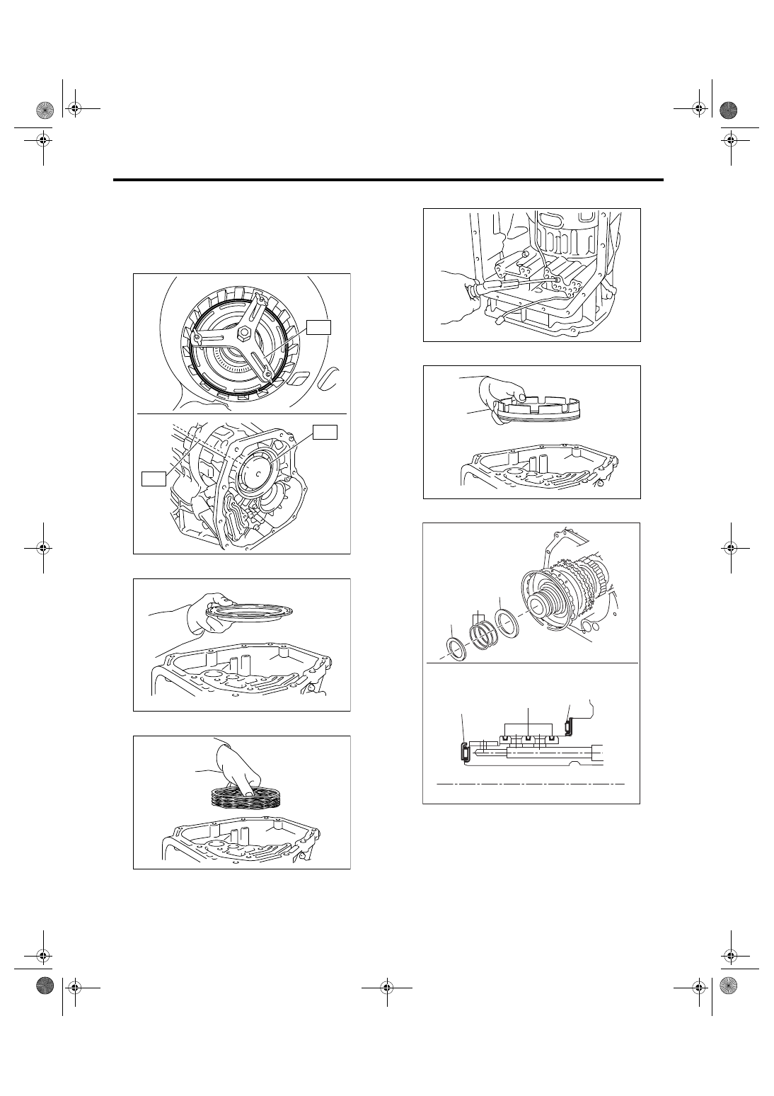
24) Remove the snap ring of the spring retainer of
reverse brake.
ST1
18762AA000 COMPRESSOR SPECIAL
TOOL
ST2
18765AA000 COMPRESSOR SUPPORT
ST3
18763AA000 COMPRESSOR SHAFT
25) Remove the spring retainer.
26) Remove the return spring.
27) Apply compressed air.
28) Remove the reverse brake piston.
29) Remove the thrust bearing and seal ring.
B: INSTALLATION
1) Apply ATF to a new seal ring.
AT-02000
ST3
ST2
ST1
AT-02001
AT-02002
(A) Thrust bearing
(B) Seal ring
AT-02004
AT-02005
(A)
(A)
(B)
(A)
(B)
(A)
AT-04306
5AT-100
AUTOMATIC TRANSMISSION
AT Main Case
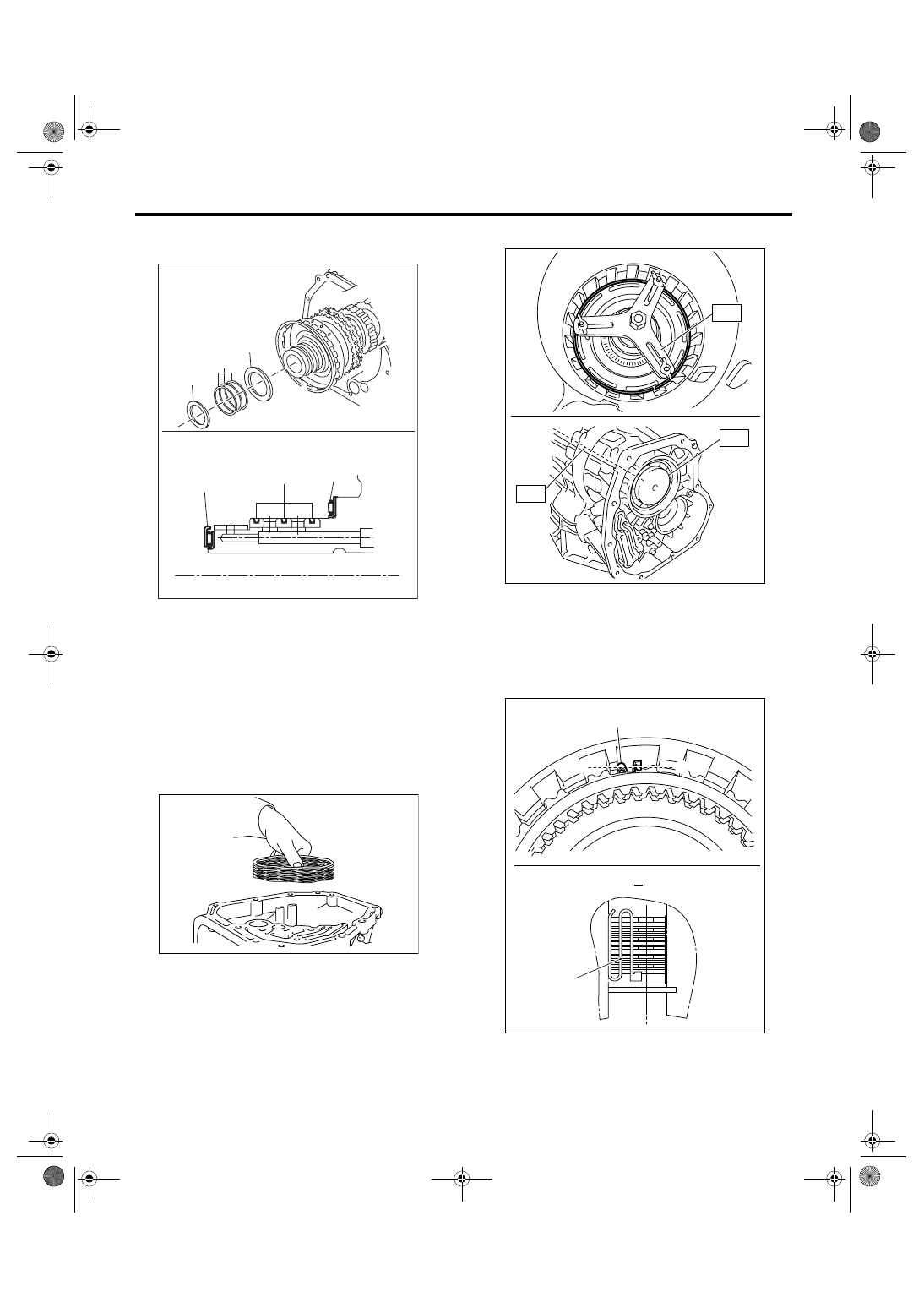
2) Install the thrust bearing and new seal ring to
drum support.
3) Install the reverse brake piston.
NOTE:
Apply ATF onto the piston sliding surface.
ST1
18762AA000 COMPRESSOR SPECIAL
TOOL
ST2
18765AA000 COMPRESSOR SUPPORT
ST3
18763AA000 COMPRESSOR SHAFT
4) Install the return spring.
5) Install the spring retainer and snap ring.
ST1
18762AA000 COMPRESSOR SPECIAL
TOOL
ST2
18765AA000 COMPRESSOR SUPPORT
ST3
18763AA000 COMPRESSOR SHAFT
6) Install the dish plate.
NOTE:
When installing, make sure that the identification
mark is facing the front side of transmission.
7) Install the drive plate and driven plate.
8) Install the leaf spring.
9) Install the retaining plate.
(A) Thrust bearing
(B) Seal ring
(A)
(A)
(B)
(A)
(B)
(A)
AT-04306
AT-02002
(A) Leaf spring
AT-02000
ST3
ST2
ST1
AT-01999
(A)
B’
B
(A)
B’
B
5AT-101
AUTOMATIC TRANSMISSION
AT Main Case
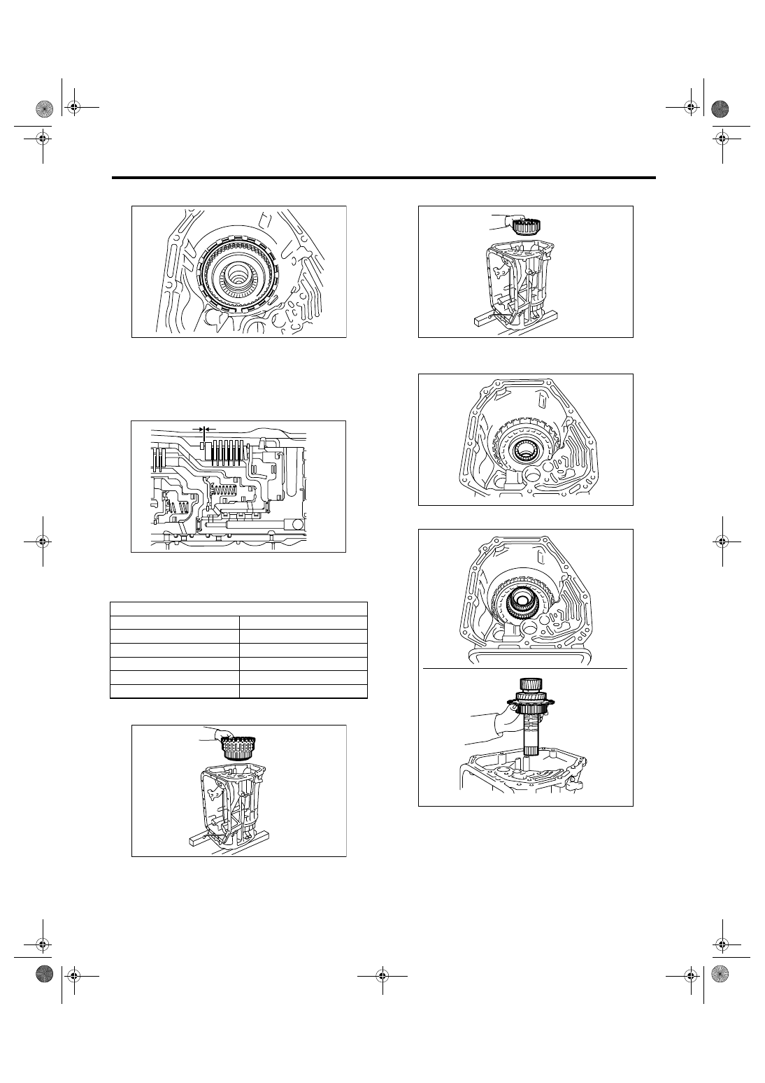
10) Install the snap ring of reverse brake.
11) Perform the clearance check of reverse brake.
(1) Measure the clearance between retainer
plate and snap ring using thickness gauge.
Specification:
0.7 — 1.1 mm (0.028 — 0.043 in)
(2) If the clearance is out of specification, select
a suitable retainer plate from following table and
assemble it.
12) Install the direct clutch assembly.
13) Install the high & low reverse clutch assembly.
14) Install the thrust needle bearing of high & low
reverse clutch.
15) Install the middle & rear sun gear assembly.
Retainer plate
Part No.
Thickness mm (in)
31567AB100
4.2 (0.165)
31567AB170
4.4 (0.173)
31567AB180
4.6 (0.181)
31567AB190
4.8 (0.189)
31567AB200
5.0 (0.197)
AT-01998
AT-02372
AT-01997
AT-01996
AT-01995
AT-01994
5AT-102
AUTOMATIC TRANSMISSION
AT Main Case
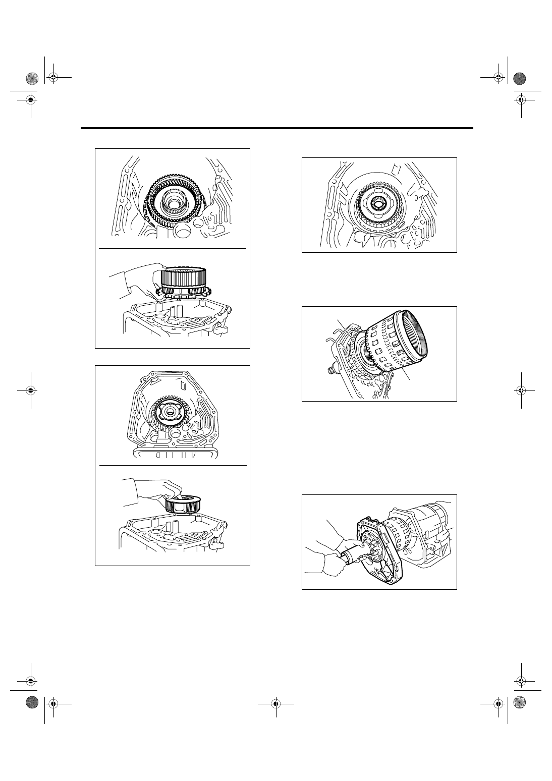
16) Install the rear carrier assembly.
17) Install the middle carrier assembly.
18) Install the thrust needle bearing of middle carri-
er assembly.
19) Measure the total end play, and select the
bearing. <Ref. to 5AT-105, ADJUSTMENT, AT
Main Case.>
20) Install the impact clutch pack assembly to oil
pump cover.
21) Turn the transmission sideways.
22) Install the oil pump cover.
(1) Apply ATF to the O-ring of input clutch shaft.
(2) Install the oil pump cover to AT main case
while supporting the input clutch shaft and oil
pump housing with your hand.
AT-01993
AT-01992
(A) Impact clutch pack ASSY
(B) Front sun gear ASSY
AT-01991
AT-02006
(A)
(B)
AT-01990
Нет комментариевНе стесняйтесь поделиться с нами вашим ценным мнением.
Текст