Subaru Legacy (2005 year). Service manual — part 591
5AT-63
AUTOMATIC TRANSMISSION
ATF Cooler Pipe and Hose
21.ATF Cooler Pipe and Hose
A: REMOVAL
1. EXCEPT FOR ATF COOLER MODEL
WITH WARMER FUNCTION
1) Set the vehicle on a lift.
2) Remove the battery.
3) Lift-up the vehicle.
4) Remove the under cover.
5) Remove the radiator under cover.
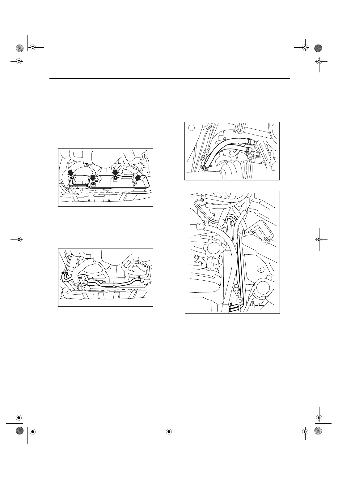
6) Disconnect the ATF cooler hose from radiator.
NOTE:
• Do not use a screwdriver or other pointed tools.
• When hard to remove the hose, wrap the hose
with cloth to prevent from damaging, and then turn
with pliers and pull out with hand straightly.
7) Disconnect the ATF cooler hoses from pipes.
NOTE:
• Do not use a screwdriver or other pointed tools.
• When hard to remove the hose, wrap the hose
with cloth to prevent from damaging, and then turn
with pliers and pull out with hand straightly.
8) Disconnect the ATF cooler pipe from frame.
AT-01344
AT-01345
AT-01388
AT-01347
5AT-64
AUTOMATIC TRANSMISSION
ATF Cooler Pipe and Hose
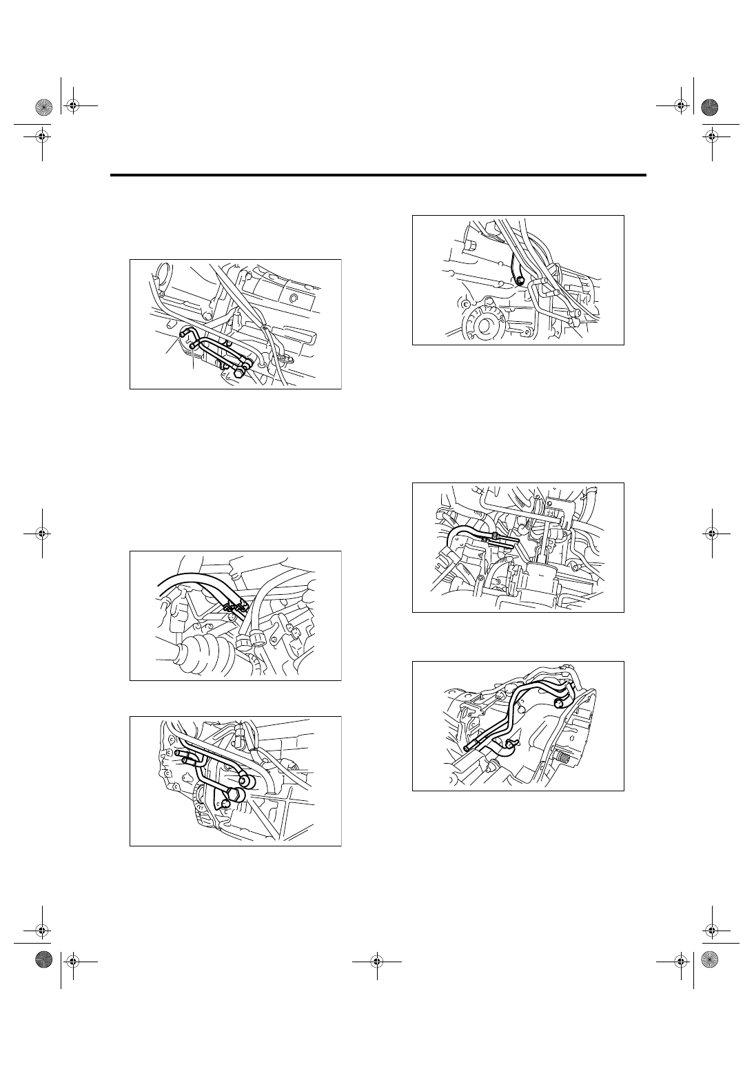
9) Remove the oil cooler inlet and outlet pipes.
NOTE:
When disconnecting the outlet pipe, be careful not
to lose the ball and spring used with retaining
screw.
2. ATF COOLER MODEL WITH WARMER
FUNCTION
1) Lift-up the vehicle.
2) Remove the front exhaust pipe.
<Ref. to EX(H6DO)-4, REMOVAL, Front Exhaust
Pipe.>
3) Disconnect the inlet and outlet of the ATF cooler
hoses from oil cooler pipe.
4) Remove the union screw of oil cooler inlet and
outlet pipes.
5) Remove the bolts which secure pipe on the side
of transmission.
6) Lower the vehicle.
7) Remove the air intake chamber.
<Ref. to IN(H6DO)-7, REMOVAL, Air Intake Cham-
ber.>
8) Remove the resonator chamber.
<Ref. to IN(H6DO)-9, REMOVAL, Resonator
Chamber.>
9) Remove the oil charge pipe. <Ref. to 5AT-69,
REMOVAL, Oil Charge Pipe.>
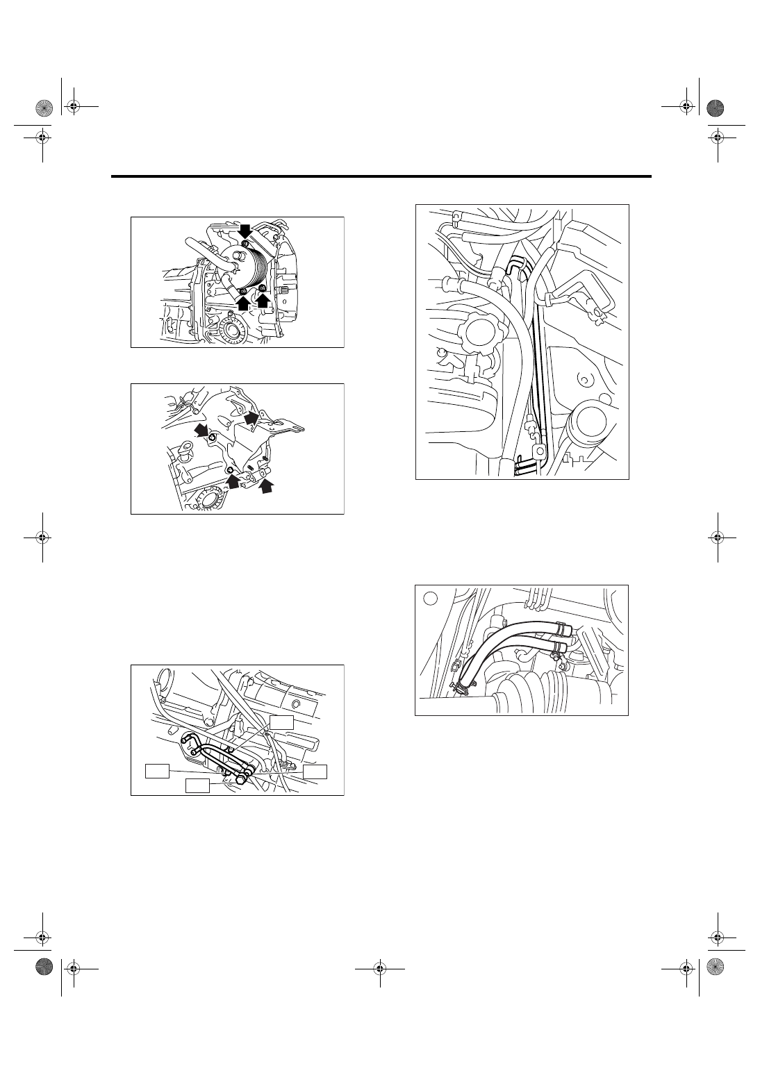
10) Disconnect the ATF cooler hoses and pipes.
11) Remove the bolt which secure pitching stopper
bracket and the bolt on the side of transmission,
and then remove ATF cooler pipe.
(A) Outlet pipe
(B) Inlet pipe
AT-01383
(A)
(B)
AT-02027
AT-02029
AT-02028
AT-02030
AT-02033
5AT-65
AUTOMATIC TRANSMISSION
ATF Cooler Pipe and Hose
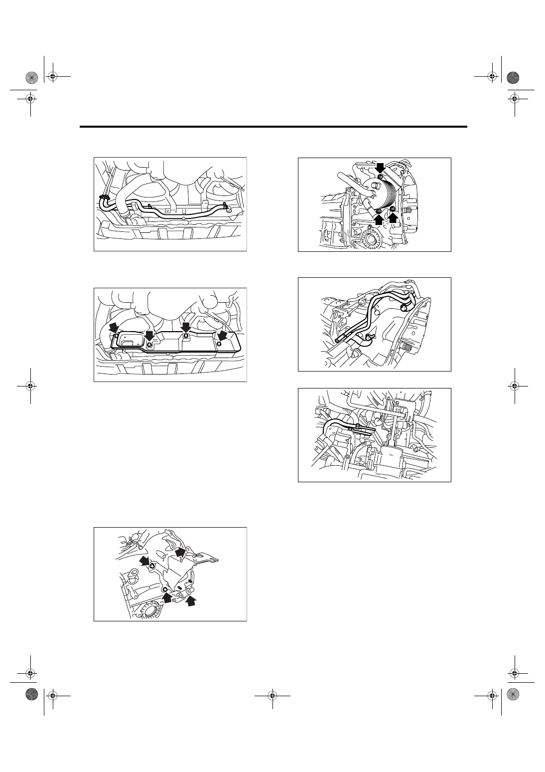
12) Remove the ATF cooler from the installation
bracket as necessary.
13) Remove the ATF cooler bracket from transmis-
sion body as necessary.
B: INSTALLATION
1. EXCEPT FOR ATF COOLER MODEL
WITH WARMER FUNCTION
1) Install the oil cooler inlet and outlet pipes with
new washer.
Tightening torque:
T1: 25 N
⋅
m (2.5 kgf-m, 18.4 ft-lb)
T2: 41 N
⋅
m (4.2 kgf-m, 30.2 ft-lb)
T3: 45 N
⋅
m (4.6 kgf-m, 33.2 ft-lb)
2) Install the ATF cooler pipe to frame.
3) Connect the ATF cooler hose to pipe on the
transmission side.
NOTE:
• Install so that the hose is not folded over, exces-
sively bent or twisted.
• Be careful to insert the hose to the specified po-
sition.
4) Connect the ATF cooler hose to pipe on the ra-
diator side.
NOTE:
• Install so that the hose is not folded over, exces-
sively bent or twisted.
AT-02031
AT-02032
AT-03133
T2
T1
T2
T3
AT-01347
AT-01388
5AT-66
AUTOMATIC TRANSMISSION
ATF Cooler Pipe and Hose
• Be careful to insert the hose to the specified po-
sition.
5) Install the radiator under cover.
Tightening torque:
4.9 N
⋅
m (0.5 kgf-m, 3.6 ft-lb)
6) Install the under cover.
7) Install the battery.
8) Fill ATF. <Ref. to 5AT-28, Automatic Transmis-
sion Fluid.>
NOTE:
Make sure there are no ATF leaks in connections of
the transmission, radiator, pipes and hoses.
2. ATF COOLER MODEL WITH WARMER
FUNCTION
1) Install the ATF cooler bracket if it is removed
from transmission body.
Tightening torque:
25 N
⋅
m (2.5 kgf-m, 18.4 ft-lb)
2) Install the ATF cooler if it is removed from instal-
lation bracket.
Tightening torque:
25 N
⋅
m (2.5 kgf-m, 18.4 ft-lb)
3) Install the pitching stopper securing bracket and
bolt in the side of transmission.
4) Install the ATF cooler hoses and pipes.
5) Connect the engine harness connectors, and
then install the engine hanger rear.
6) Install the oil charge pipe. <Ref. to 5AT-69, IN-
STALLATION, Oil Charge Pipe.>
7) Install the resonator chamber.
<Ref. to IN(H6DO)-9, INSTALLATION, Resonator
Chamber.>
8) Install the air intake chamber.
<Ref. to IN(H6DO)-7, INSTALLATION, Air Intake
Chamber.>
9) Lift-up the vehicle.
AT-01345
AT-01344
AT-02032
AT-02031
AT-02033
AT-02030
Нет комментариевНе стесняйтесь поделиться с нами вашим ценным мнением.
Текст