Subaru Legacy (2005 year). Service manual — part 589
5AT-55
AUTOMATIC TRANSMISSION
Rear Vehicle Speed Sensor
16) Lower the transmission jack.
NOTE:
Do not separate the transmission jack and trans-
mission.
17) Remove the oil charge pipe. <Ref. to 5AT-69,
REMOVAL, Oil Charge Pipe.>
18) Remove the ATF cooler inlet and outlet pipes.
NOTE:
When removing the outlet pipe, be careful not to
lose the ball and spring used with retaining screw.
19) Disconnect the connector from turbine speed
sensor 1.
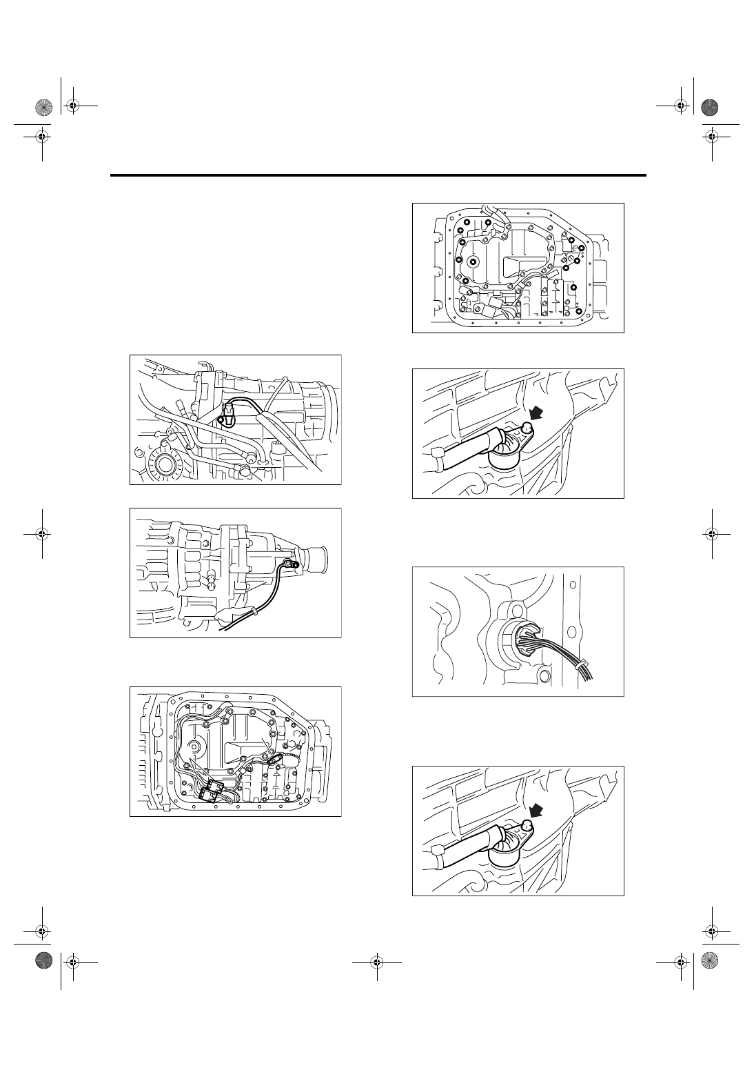
20) Remove the rear vehicle speed sensor.
21) Remove the oil pan.
22) Disconnect the control valve connector and
front vehicle speed sensor connector.
23) Remove the control valve body.
24) Remove the bolt securing harness of transmis-
sion main case.
25) Remove the harness assembly.
B: INSTALLATION
1) Pass the harness assembly through the hole in
transmission case.
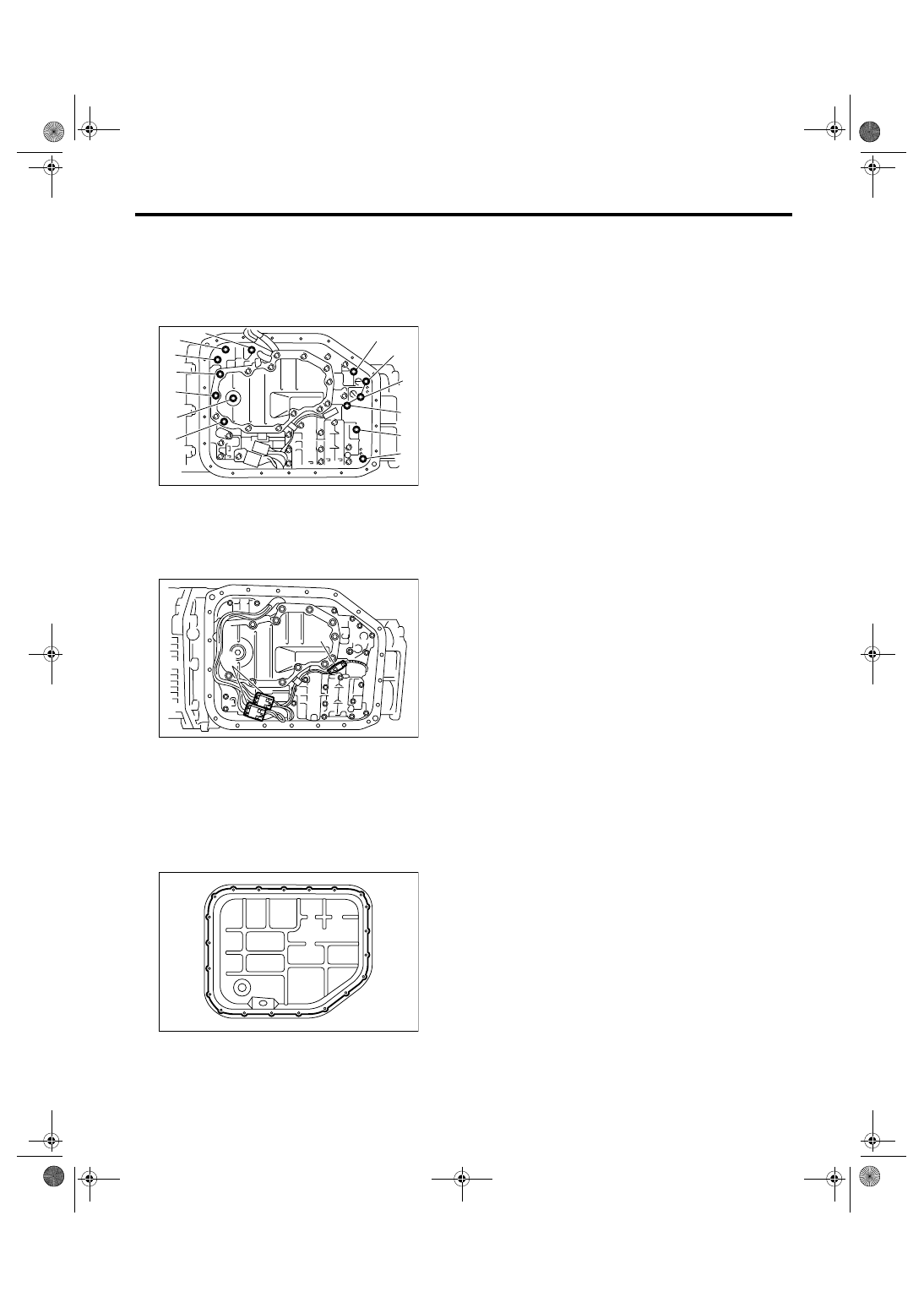
2) Install the securing bolt of transmission main
case.
Tightening torque:
7 N
⋅
m (0.7 kgf-m, 5.2 ft-lb)
(A) Control valve connector
(B) Front vehicle speed sensor connector
AT-01387
AT-01950
AT-01956
(B)
(A)
AT-01957
AT-02035
AT-00048
AT-02035
5AT-56
AUTOMATIC TRANSMISSION
Rear Vehicle Speed Sensor
3) Install the control valve body.
Tightening torque:
8 N
⋅
m (0.8 kgf-m, 5.9 ft-lb)
NOTE:
Be careful not to catch harness in.
4) Connect the control valve connector and front
vehicle speed sensor connector.
5) Apply proper amount of liquid gasket to the en-
tire oil pan mating surface.
Liquid gasket:
THREE BOND 1217B (Part No. K0877YA020)
6) Install the oil pan by equally tightening the bolts.
Tightening torque:
5 N
⋅
m (0.5 kgf-m, 3.7 ft-lb)
7) Install the rear vehicle speed sensor and turbine
speed sensor 1, and then fasten the harness.
Tightening torque:
7 N
⋅
m (0.7 kgf-m, 5.2 ft-lb)
8) Install a new aluminum washer and oil cooler
pipe.
Tightening torque:
25 N
⋅
m (2.5 kgf-m, 18.4 ft-lb)
9) Install the oil charge pipe. <Ref. to 5AT-69, IN-
STALLATION, Oil Charge Pipe.>
10) Install the transmission rear crossmember bolt.
Tightening torque:
70 N
⋅
m (7.1 kgf-m, 51.6 ft-lb)
11) Install the propeller shaft. <Ref. to DS-11, IN-
STALLATION, Propeller Shaft.>
12) Install the heat shield cover.
13) Install the center exhaust pipe, rear exhaust
pipe and muffler. (Turbo model)
<Ref. to EX(H4DOTC)-7, INSTALLATION, Center
Exhaust Pipe.> <Ref. to EX(H4DOTC)-11, IN-
STALLATION, Rear Exhaust Pipe.> <Ref. to
EX(H4DOTC)-12, INSTALLATION, Muffler.>
14) Install the rear exhaust pipe and muffler. (Non-
turbo model) <Ref. to EX(H6DO)-7, INSTALLA-
TION, Rear Exhaust Pipe.> <Ref. to EX(H6DO)-9,
INSTALLATION, Muffler.>
15) Lower the vehicle.
16) Install the transmission connector to the stay,
and then connect the connector.
17) Install the intercooler. (Turbo model) <Ref. to
IN(H4DOTC)-12, INSTALLATION, Intercooler.>
18) Install the air intake chamber. (Non-turbo mod-
el) <Ref. to IN(H6DO)-7, INSTALLATION, Air In-
take Chamber.>
19) Pour ATF from the oil charge pipe. <Ref. to
5AT-28, REPLACEMENT, Automatic Transmis-
sion Fluid.>
20) Check the level and leaks of ATF. <Ref. to 5AT-
28, INSPECTION, Automatic Transmission Fluid.>
21) Execute the learning control promotion. <Ref.
to 5AT(diag)-23, PROCEDURE, Learning Con-
trol.>
(1) 58 mm (2.28 in)
(2) 65 mm (2.56 in)
(A) Control valve connector
(B) Front vehicle speed sensor connector
AT-01958
(1)
(1)
(1)
(2)
(2)
(2)
(2)
(1)
(1)
(1)
(1)
(1)
(2)
AT-01956
(B)
(A)
AT-01955
5AT-57
AUTOMATIC TRANSMISSION
Turbine Speed Sensor 1
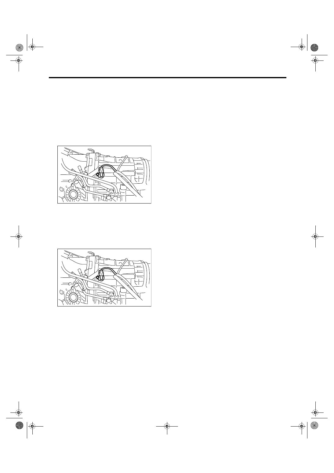
16.Turbine Speed Sensor 1
A: REMOVAL
1) Lift-up the vehicle.
2) Remove the intercooler. (Turbo model) <Ref. to
IN(H4DOTC)-12, REMOVAL, Intercooler.>
3) Remove the air intake chamber. (Non-turbo
model) <Ref. to IN(H6DO)-7, REMOVAL, Air Intake
Chamber.>
4) Disconnect the turbine speed sensor 1 connec-
tor.
5) Remove the turbine speed sensor 1.
B: INSTALLATION
1) Install the turbine speed sensor 1.
Tightening torque:
7 N
⋅
m (0.7 kgf-m, 5.2 ft-lb)
2) Connect the turbine speed sensor 1 connector.
3) Install the intercooler. (Turbo model) <Ref. to
IN(H4DOTC)-12, INSTALLATION, Intercooler.>
4) Install the air intake chamber. (Non-turbo model)
<Ref. to IN(H6DO)-7, INSTALLATION, Air Intake
Chamber.>
AT-01387
AT-01387
5AT-58
AUTOMATIC TRANSMISSION
Control Valve Body
17.Control Valve Body
A: REMOVAL
1) Set the vehicle on a lift.
2) Disconnect the ground cable from battery.
3) Lift-up the vehicle.
4) Clean the transmission exterior.
5) Remove the ATF drain plug to drain ATF.
CAUTION:
Directly after the vehicle has been running, the
ATF is hot. Be careful not to burn yourself.
6) Tighten the ATF drain plug.
NOTE:
Use a new gasket.
Tightening torque:
25 N
⋅
m (2.5 kgf-m, 18.4 ft-lb)
7) Remove the oil pan.
CAUTION:
Be sure to prevent the entering of dust and oth-
er foreign matters into oil pan.
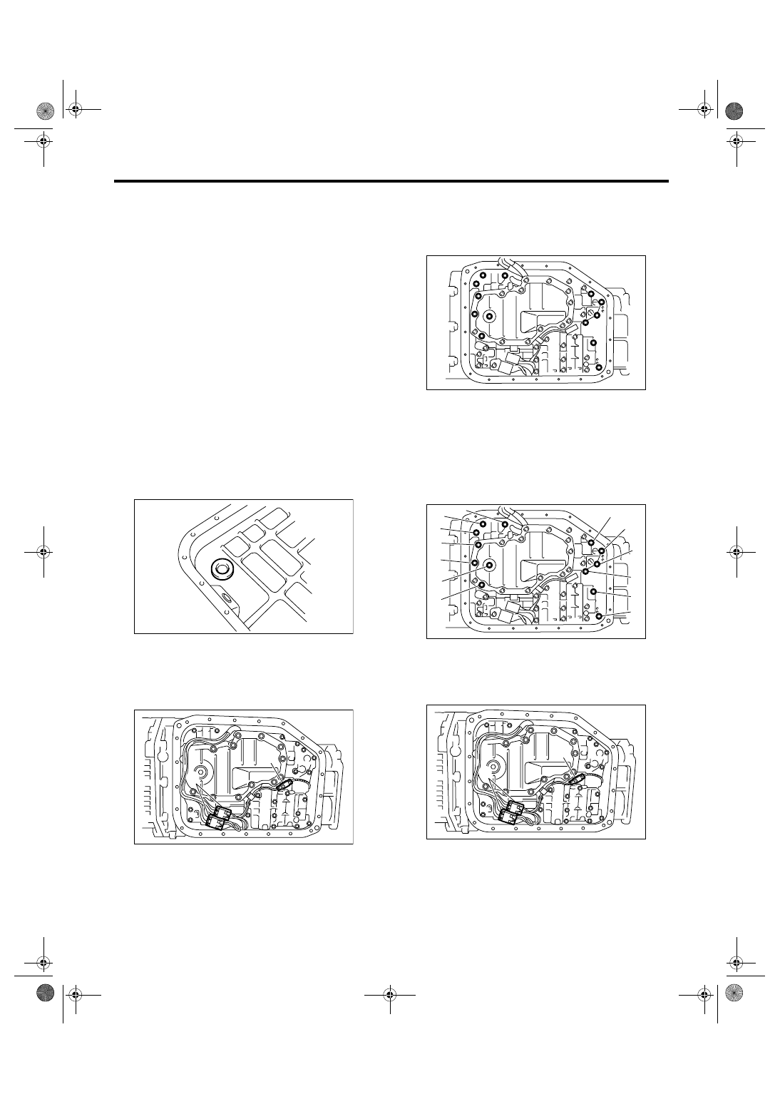
8) Remove the magnet.
9) Clean the magnet.
10) Completely remove the remaining liquid gasket
on the transmission case and oil pan.
11) Disconnect the control valve connector and
front vehicle speed sensor connector.
12) Remove the control valve body.
NOTE:
Replace the control valve body as assembly, be-
cause it is a non-disassemble part.
B: INSTALLATION
1) Check the control valve body for dust and other
foreign matters.
2) Install the control valve body to transmission by
equally tightening the bolts.
Tightening torque:
8 N
⋅
m (0.8 kgf-m, 5.9 ft-lb)
3) Connect the control valve connector.
(A) Control valve connector
(B) Front vehicle speed sensor connector
AT-01959
AT-01956
(B)
(A)
(1) 58 mm (2.28 in)
(2) 65 mm (2.56 in)
(A) Control valve connector
(B) Front vehicle speed sensor connector
AT-01957
AT-01958
(1)
(1)
(1)
(2)
(2)
(2)
(2)
(1)
(1)
(1)
(1)
(1)
(2)
AT-01956
(B)
(A)
Нет комментариевНе стесняйтесь поделиться с нами вашим ценным мнением.
Текст