Subaru Legacy (2005 year). Service manual — part 592
5AT-67
AUTOMATIC TRANSMISSION
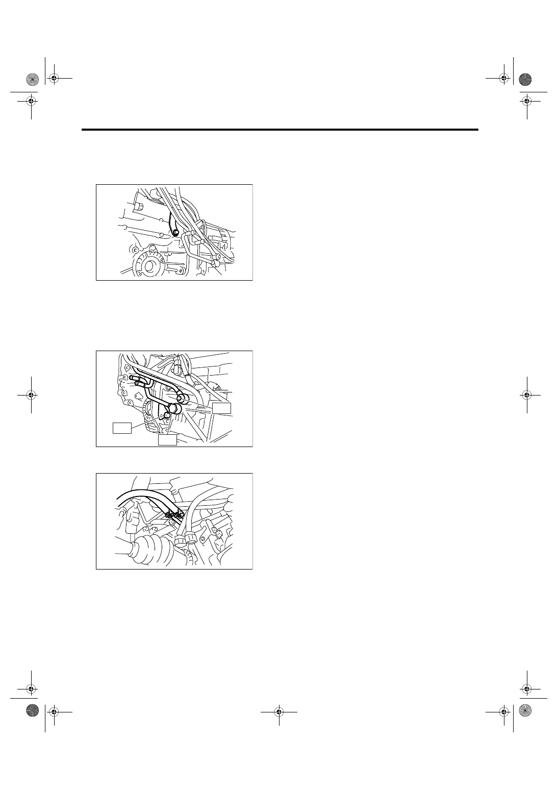
ATF Cooler Pipe and Hose
10) Install the pipe securing bolts on the side of
transmission.
Tightening torque:
25 N
⋅
m (2.5 kgf-m, 18.4 ft-lb)
11) Install the union screw of oil cooler inlet and
outlet pipes.
Tightening torque:
T1: 25 N
⋅
m (2.5 kgf-m, 18.4 ft-lb)
T2: 41 N
⋅
m (4.2 kgf-m, 30.2 ft-lb)
T3: 45 N
⋅
m (4.6 kgf-m, 33.2 ft-lb)
12) Install the inlet and outlet pipes of ATF oil cool-
er hose to oil cooler pipe.
13) Install the front exhaust pipe.
<Ref. to EX(H6DO)-5, INSTALLATION, Front Ex-
haust Pipe.>
C: INSPECTION
Repair or replace any defective hoses, pipes,
clamps, and washers found during the inspection
below.
1) Check for ATF leaks in connections of the trans-
mission, radiator, pipes and hoses.
2) Check for deformed clamps.
3) Lightly bend the hose and check for cracks in the
surface or other damages.
4) Pinch the hose with your fingers and check for
poor elasticity. Also check for poor elasticity in the
parts where the clamp was installed by pressing
with your fingernail.
5) Check for peeling, cracks, and deformation at
the tip of the hose.
6) Check the ATF cooler for cracks or deformation.
(ATF cooler model with warmer function)
AT-02028
AT-03134
T2
T1
T3
AT-02027
5AT-68
AUTOMATIC TRANSMISSION
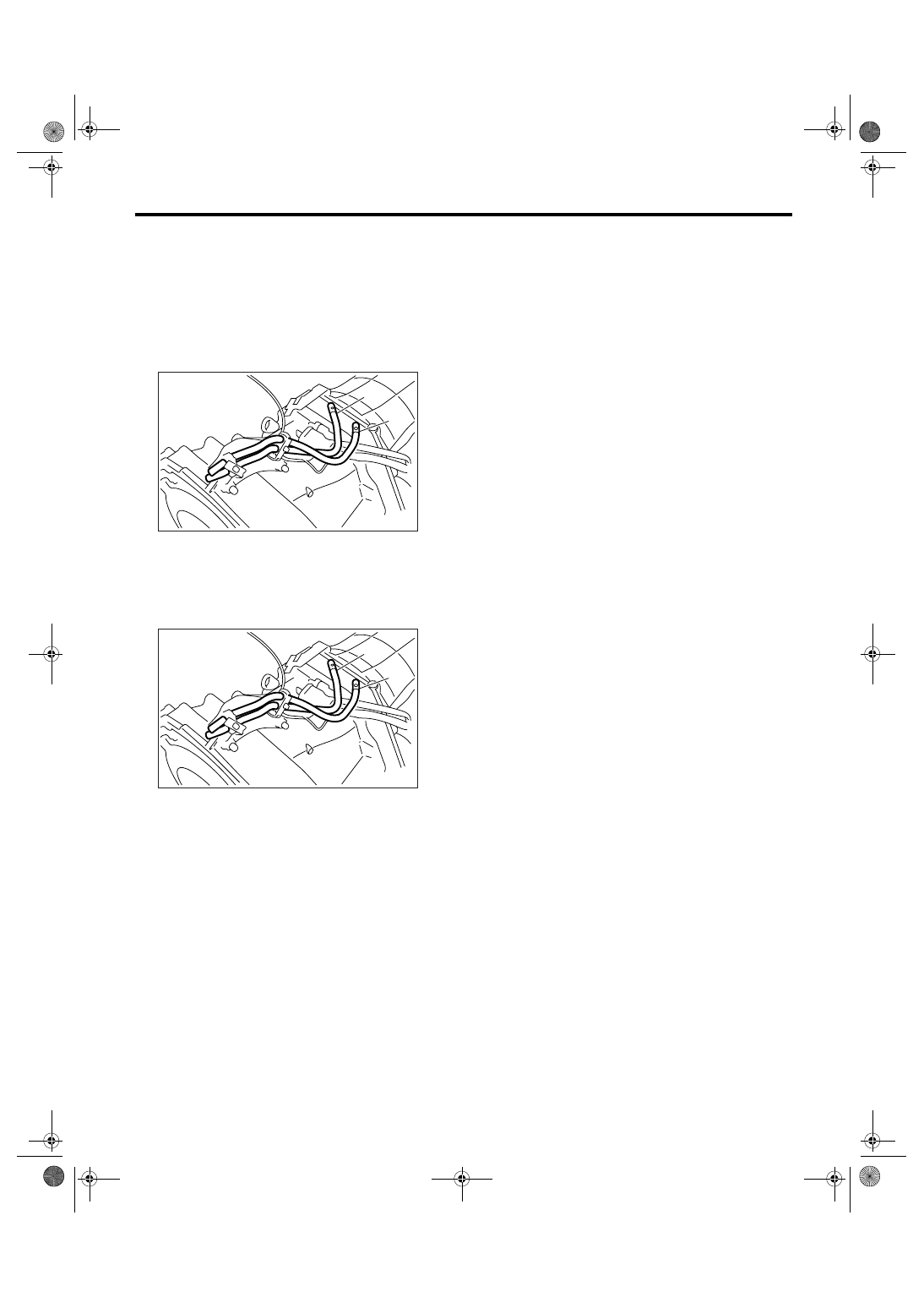
Air Breather Hose
22.Air Breather Hose
A: REMOVAL
1) Remove the intercooler. (Turbo model) <Ref. to
IN(H4DOTC)-12, REMOVAL, Intercooler.>
2) Remove the air intake chamber. (Non-turbo
model) <Ref. to IN(H6DO)-7, REMOVAL, Air Intake
Chamber.>
3) Disconnect the air breather hose.
B: INSTALLATION
1) Connect the air breather hose.
2) Install the intercooler. (Turbo model) <Ref. to
IN(H4DOTC)-12, INSTALLATION, Intercooler.>
3) Install the air intake chamber. (Non-turbo model)
<Ref. to IN(H6DO)-7, INSTALLATION, Air Intake
Chamber.>
C: INSPECTION
Make sure the hose is not cracked or clogged.
(A) Air breather hose (Transmission case)
(B) Air breather hose (Oil pump cover)
(A) Air breather hose (Transmission case)
(B) Air breather hose (Oil pump cover)
(A)
AT-01385
(B)
(A)
AT-01385
(B)
5AT-69
AUTOMATIC TRANSMISSION
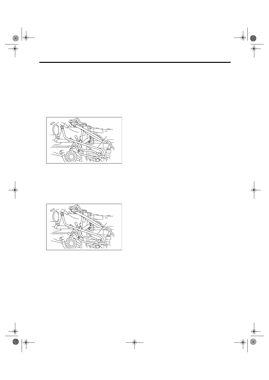
Oil Charge Pipe
23.Oil Charge Pipe
A: REMOVAL
1) Remove the intercooler. (Turbo model)
<Ref. to IN(H4DOTC)-12, REMOVAL, Intercool-
er.>
2) Remove the air intake chamber. (Non-turbo
model) <Ref. to IN(H6DO)-7, REMOVAL, Air Intake
Chamber.>
3) Remove the oil charge pipe, and then remove
the O-ring from flange side.
B: INSTALLATION
1) Install the oil charge pipe with a new O-ring.
Tightening torque:
41 N
⋅
m (4.2 kgf-m, 30.2 ft-lb)
2) Install the intercooler. (Turbo model) <Ref. to
IN(H4DOTC)-12, INSTALLATION, Intercooler.>
3) Install the air intake chamber. (Non-turbo model)
<Ref. to IN(H6DO)-7, INSTALLATION, Air Intake
Chamber.>
C: INSPECTION
Make sure the oil charge pipe is not deformed or
damaged.
(A) Oil level gauge
(B) Oil charge pipe
(A) Oil level gauge
(B) Oil charge pipe
AT-01386
(B)
(A)
AT-01386
(B)
(A)
5AT-70
AUTOMATIC TRANSMISSION
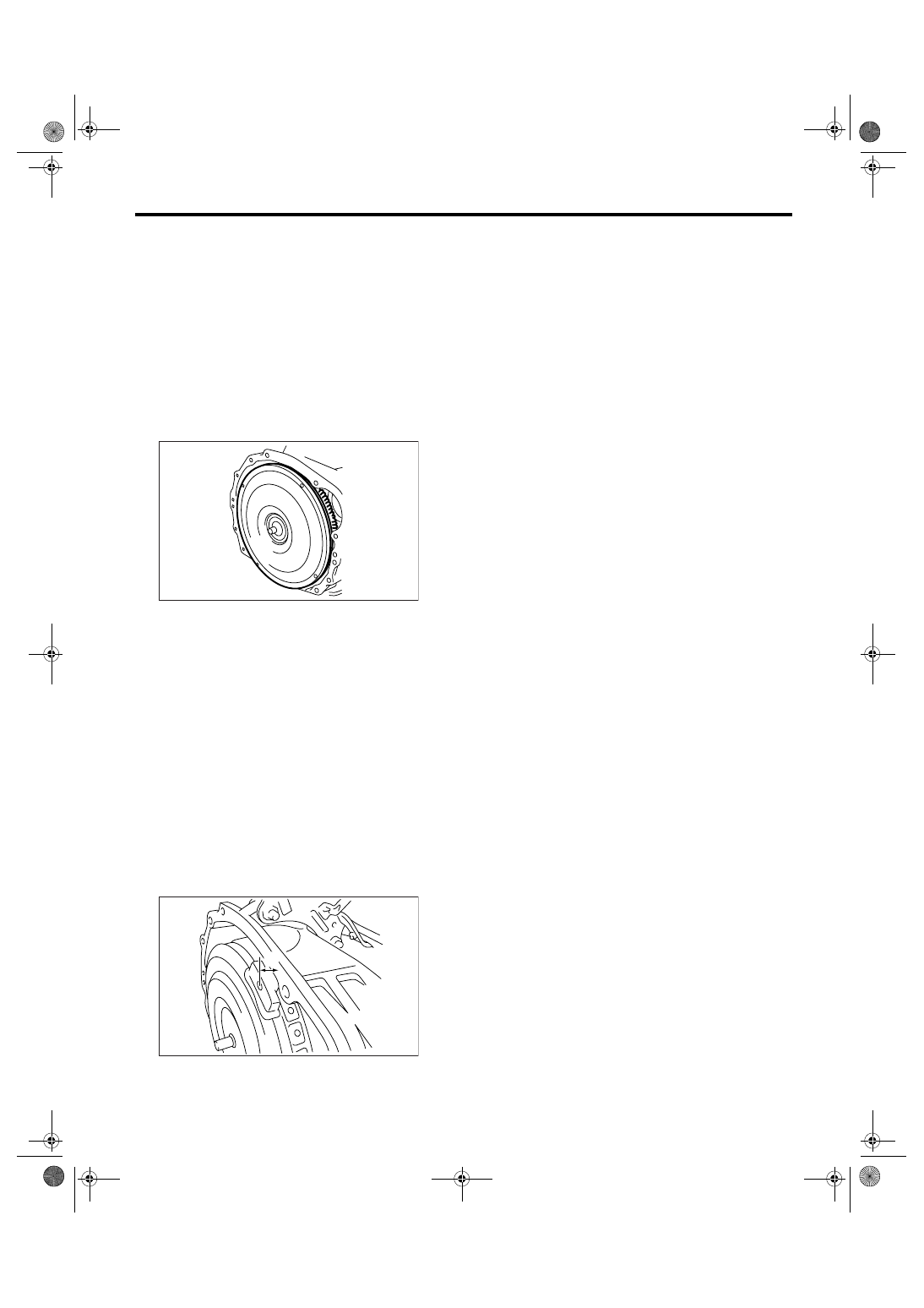
Torque Converter Assembly
24.Torque Converter Assembly
A: REMOVAL
1) Remove the transmission assembly from vehi-
cle. <Ref. to 5AT-38, REMOVAL, Automatic Trans-
mission Assembly.>
2) Pull out the torque converter and oil pump shaft
horizontally.
NOTE:
• Be sure not to scratch the inside of bushing in oil
pump shaft.
• Be careful that the oil pump shaft may drawn out
simultaneously.
3) Remove the oil pump shaft from torque convert-
er as necessary.
B: INSTALLATION
1) When the oil pump shaft is removed, install the
shaft to torque converter.
NOTE:
Make sure the clip is firmly inserted.
2) Install the oil pump shaft to torque converter, and
then make sure that the clip is secured on groove.
3) Apply ATF to the revolution and sliding surface
oil pump shaft.
4) Holding the torque converter assembly by hand,
lightly rotate it to engage with the oil pump rotor.
5) Check the protruding dimension of torque con-
verter assembly.
Dimension A:
8 mm (0.31 in) or less
6) Install the transmission assembly into vehicle.
<Ref. to 5AT-42, INSTALLATION, Automatic
Transmission Assembly.>
C: INSPECTION
Make sure the ring gear and protrusion of torque
converter end are not deformed or damaged.
(A) Dimension A
AT-00113
AT-01641
(A)
Нет комментариевНе стесняйтесь поделиться с нами вашим ценным мнением.
Текст