Subaru Legacy (2005 year). Service manual — part 348
EN(H4DOTC)(diag)-161
ENGINE (DIAGNOSTICS)
Diagnostic Procedure with Diagnostic Trouble Code (DTC)
BA:DTC P0852 PARK/NEUTRAL SWITCH INPUT CIRCUIT HIGH
DTC DETECTING CONDITION:
Detects when malfunction occurs in 2 continuous driving cycles.
TROUBLE SYMPTOM:
Erroneous idling
CAUTION:
After repair or replacement of faulty parts, perform Clear Memory Mode <Ref. to EN(H4DOTC)(diag)-
37, OPERATION, Clear Memory Mode.> and Inspection Mode <Ref. to EN(H4DOTC)(diag)-30, PROCE-
DURE, Inspection Mode.>.
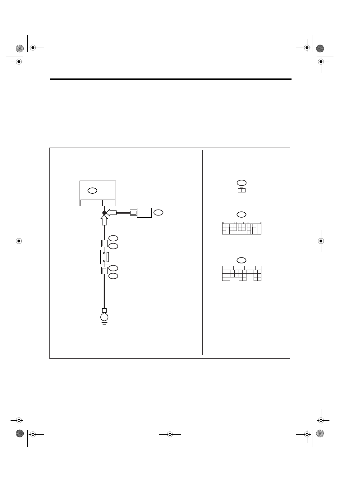
WIRING DIAGRAM:
ECM
9
2
B25
T2
T2
B25
1
EN-03558
B55
NEUTRAL
POSITION
SWITCH
B137
19
TCM
B55
B137
5
6
7
8
2
1
9
4
3
10
22 23
11 12 13 14 15
24 25
26
16 17
18 19 20 21
27
28 29
30 31
AT
MT
1 2 3 4
10 11 12
19 20 21
13
5 6
14 15
7
8
9
16
17
18
22
23
24
E
B25
1 2
EN(H4DOTC)(diag)-162
ENGINE (DIAGNOSTICS)
Diagnostic Procedure with Diagnostic Trouble Code (DTC)
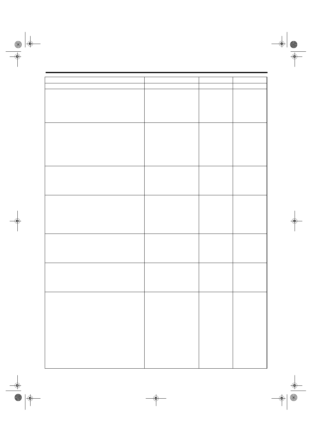
Step
Check
Yes
No
1
CHECK TRANSMISSION TYPE.
Is the transmission type AT?
2
CHECK DTC.
Check the DTC of AT.
Is DTC of AT displayed?
Perform the diag-
nosis for AT. <Ref.
to 5AT(diag)-35,
Diagnostic Proce-
dure with Diagnos-
tic Trouble Code
(DTC).>
3
CHECK HARNESS BETWEEN ECM AND
TCM.
1) Turn the ignition switch to OFF.
2) Disconnect the connector from ECM and
TCM.
3) Measure the resistance of harness
between ECM and TCM.
Connector & terminal
(B137) No. 9 — (B55) No. 19:
Is the resistance less than 1
Ω?
Repair the open
circuit of harness
between ECM and
TCM.
4
CHECK HARNESS BETWEEN ECM AND
TCM.
Measure the resistance between ECM and
chassis ground.
Connector & terminal
(B137) No. 9 — Chassis ground:
Is the resistance more than 1
M
Ω?
Repair the poor
contact in ECM
and TCM connec-
tor.
Repair the ground
short circuit of har-
ness between
ECM and TCM.
5
CHECK INPUT SIGNAL OF ECM.
1) Turn the ignition switch to ON.
2) Place the shift lever except in neutral posi-
tion.
3) Measure the voltage between ECM and
chassis ground.
Connector & terminal
(B137) No. 9 (+) — Chassis ground (
−
):
Is the voltage less than 1 V?
6
CHECK INPUT SIGNAL OF ECM.
1) Place the shift lever in neutral position.
2) Measure the voltage between ECM and
chassis ground.
Connector & terminal
(B137) No. 9 (+) — Chassis ground (
−
):
Is the voltage more than 10 V? Repair the poor
contact in ECM
connector.
7
CHECK INPUT SIGNAL OF ECM.
1) Disconnect the connector from ECM.
2) Measure the voltage between ECM and
chassis ground.
Connector & terminal
(B137) No. 9 (+) — Chassis ground (
−
):
Is the voltage more than 10 V? Repair the battery
short circuit of har-
ness between
ECM and trans-
mission harness
connector.
8
CHECK HARNESS BETWEEN ECM AND
TRANSMISSION HARNESS CONNECTOR.
1) Turn the ignition switch to OFF.
2) Disconnect the connectors from ECM and
transmission harness connector (T9).
3) Measure the resistance of harness
between ECM and neutral position switch con-
nector.
Connector & terminal
(B137) No. 9 — (B25) No. 1:
Is the resistance less than 1
Ω?
Repair the har-
ness and connec-
tor.
NOTE:
In this case, repair
the following:
• Open circuit of
harness between
ECM and trans-
mission harness
connector
• Poor contact in
transmission har-
ness connector
• Poor contact in
ECM connector
EN(H4DOTC)(diag)-163
ENGINE (DIAGNOSTICS)
Diagnostic Procedure with Diagnostic Trouble Code (DTC)
BB:DTC P1160 RETURN SPRING FAILURE
NOTE:
For the diagnostic procedure, refer to DTC P2101. <Ref. to EN(H4DOTC)(diag)-183, DTC P2101 THROT-
TLE ACTUATOR CONTROL MOTOR CIRCUIT RANGE/PERFORMANCE, Diagnostic Procedure with Di-
agnostic Trouble Code (DTC).>
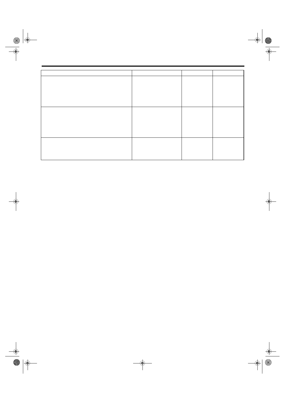
9
CHECK HARNESS BETWEEN NEUTRAL
POSITION SWITCH AND ENGINE.
Measure the resistance of harness between
transmission harness connector and engine
ground.
Connector & terminal
(B25) No. 2 — Engine ground:
Is the resistance less than 1
Ω?
Repair the open
circuit in the neu-
tral position switch
ground line.
10
CHECK NEUTRAL POSITION SWITCH.
1) Place the shift lever except in neutral posi-
tion.
2) Measure the resistance between transmis-
sion harness connector socket terminals.
Terminals
No. 1 — No. 2:
Is the resistance less than 1
Ω?
Replace the neu-
tral position switch.
11
CHECK POOR CONTACT.
Check poor contact in transmission harness
connector.
Is there poor contact in trans-
mission harness connector?
Repair the poor
contact in trans-
mission harness
connector.
Replace the ECM.
<Ref. to
FU(H4DOTC)-34,
Engine Control
Module (ECM).>
Step
Check
Yes
No
EN(H4DOTC)(diag)-164
ENGINE (DIAGNOSTICS)
Diagnostic Procedure with Diagnostic Trouble Code (DTC)
BC:DTC P1518 STARTER SWITCH CIRCUIT LOW INPUT
DTC DETECTING CONDITION:
Detects when malfunction occurs in 2 continuous driving cycles.
TROUBLE SYMPTOM:
Failure of engine to start
CAUTION:
After repair or replacement of faulty parts, perform Clear Memory Mode <Ref. to EN(H4DOTC)(diag)-
37, OPERATION, Clear Memory Mode.> and Inspection Mode <Ref. to EN(H4DOTC)(diag)-30, PROCE-
DURE, Inspection Mode.>.
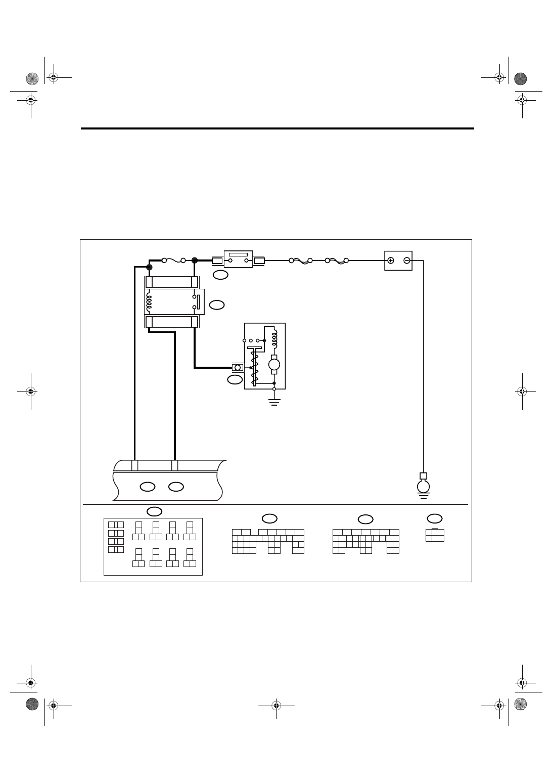
WIRING DIAGRAM:
EN-03518
No.21
B225
B225
MAIN SBF
SBF-6
E
16
14
15
13
ECM
B137
D:
B135
B:
B137
B72
D:
B135
B:
B32
D8
B72
B14
3
2
M
10
11 12
13
14
15 16
17
18
19 20
21
22
23 24
25
26
27 28
29
30
31 32
33
34
35 36
39 40
37
38
1
2
9
3
4
5
6
7
8
1
2
7
8 9
5
6
3
4
10 11 12
19 20 21
29
30 31
13 14 15 16 17
27
28
18
22 23
24 25
26
1
2
7
8 9
5
6
3
4
10 11 12
19
20 21
29 30 31
13 14 15 16 17
27
28
18
22 23
24 25
26
32 33
34 35
1
3
4 5 6
2
BATTERY
IGNITION
SWITCH
STARTER RELAY
STARTER MOTOR
Нет комментариевНе стесняйтесь поделиться с нами вашим ценным мнением.
Текст