Subaru Legacy (2005 year). Service manual — part 346
EN(H4DOTC)(diag)-153
ENGINE (DIAGNOSTICS)
Diagnostic Procedure with Diagnostic Trouble Code (DTC)
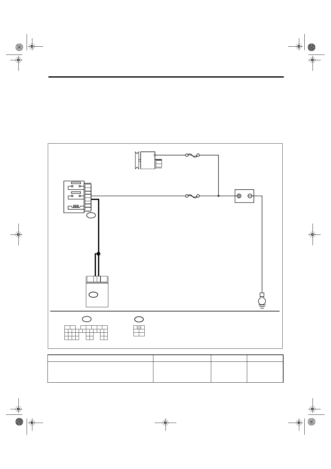
AS:DTC P0563 SYSTEM VOLTAGE HIGH
DTC DETECTING CONDITION:
Detects when the power supply voltage of ECM is high.
TROUBLE SYMPTOM:
Charge indicator light illuminates.
CAUTION:
After repair or replacement of faulty parts, perform Clear Memory Mode <Ref. to EN(H4DOTC)(diag)-
37, OPERATION, Clear Memory Mode.> and Inspection Mode <Ref. to EN(H4DOTC)(diag)-30, PROCE-
DURE, Inspection Mode.>.
WIRING DIAGRAM:
Step
Check
Yes
No
1
CHECK BATTERY.
1) Turn the ignition switch to OFF.
2) Measure the battery voltage and specific
gravity of electrolyte.
Is the voltage more than 12 V
and the specific gravity more
than 1.26?
Replace the bat-
tery.
EN-03528
B47
E
SBF-7
MAIN SBF
B47
B135
ECM
5
6
5
4
6
3
2
1
3
4
1
2
5
6
B135
GENERATOR
MAIN RELAY
BATTERY
5
6
7
8
2
1
9
4
3
10
24
22 23
25
11 12 13 14 15
26 27
28
16 17 18 19
20 21
29 30 31
32 33
34 35

EN(H4DOTC)(diag)-154
ENGINE (DIAGNOSTICS)
Diagnostic Procedure with Diagnostic Trouble Code (DTC)
2
CHECK GENERATOR.
1) Start the engine.
2) Run the engine at idle after warming up.
3) Measure the voltage between generator B
terminal and chassis ground.
Terminals
Generator B terminal (+) — Chassis
ground (
−
):
Is the voltage less than 16.2
V?
Repair the genera-
tor. <Ref. to
SC(H4SO 2.0)-14,
Generator.>
3
CHECK GENERATOR.
1) Run the engine at 5,000 rpm.
2) Measure the voltage between generator B
terminal and chassis ground.
Terminals
Generator B terminal (+) — Chassis
ground (
−
):
Is the voltage less than 16.2
V?
Repair the genera-
tor. <Ref. to
SC(H4SO 2.0)-14,
Generator.>
4
CHECK BATTERY TERMINAL.
1) Turn the ignition switch to OFF.
2) Check the installation of positive and nega-
tive terminals of battery.
Are the positive and negative
battery terminals clamped
tightly?
Tighten the clamp
of terminal.
5
CHECK INPUT VOLTAGE OF ECM.
1) Run the engine at idle.
2) Measure the voltage between ECM con-
nector and chassis ground.
Connector & terminal
(B135) No. 5 (+) — Chassis ground (
−
):
(B135) No. 6 (+) — Chassis ground (
−
):
Is the voltage less than 16.2
V?
Repair the har-
ness connectors
between battery,
main relay and
ECM.
6
CHECK POOR CONTACT IN CONNECTORS.
Check the poor contact in connectors between
generator, battery and ECM.
Is there poor contact in con-
nectors between generator,
battery and ECM?
Repair the poor
contact.
7
CHECK ECM.
1) Connect all the connectors.
2) Perform the clear memory mode. <Ref. to
EN(H4DOTC)(diag)-37, Clear Memory Mode.>
3) Perform the inspection mode. <Ref. to
EN(H4DOTC)(diag)-30, Inspection Mode.>
4) Read the DTC. <Ref. to
EN(H4DOTC)(diag)-29, Read Diagnostic Trou-
ble Code (DTC).>
Check if the same DTC is displayed.
Is the same DTC displayed?
Replace the gen-
erator.
8
CHECK OTHER DTC DETECTION.
Check if any other DTC is displayed.
Is any other DTC displayed?
Perform the diag-
nosis of DTC dis-
played.
Temporary poor
contact occurs.
Step
Check
Yes
No
EN(H4DOTC)(diag)-155
ENGINE (DIAGNOSTICS)
Diagnostic Procedure with Diagnostic Trouble Code (DTC)
AT:DTC P0600 SERIAL COMMUNICATION LINK
NOTE:
For the diagnostic procedure, refer to LAN system.
AU:DTC P0604 INTERNAL CONTROL MODULE RANDOM ACCESS MEMORY
(RAM) ERROR
NOTE:
For the diagnostic procedure, refer to DTC P0607. <Ref. to EN(H4DOTC)(diag)-155, DTC P0607 CONTROL
MODULE PERFORMANCE, Diagnostic Procedure with Diagnostic Trouble Code (DTC).>
AV:DTC P0605 INTERNAL CONTROL MODULE READ ONLY MEMORY (ROM)
ERROR
NOTE:
For the diagnostic procedure, refer to DTC P0607. <Ref. to EN(H4DOTC)(diag)-155, DTC P0607 CONTROL
MODULE PERFORMANCE, Diagnostic Procedure with Diagnostic Trouble Code (DTC).>
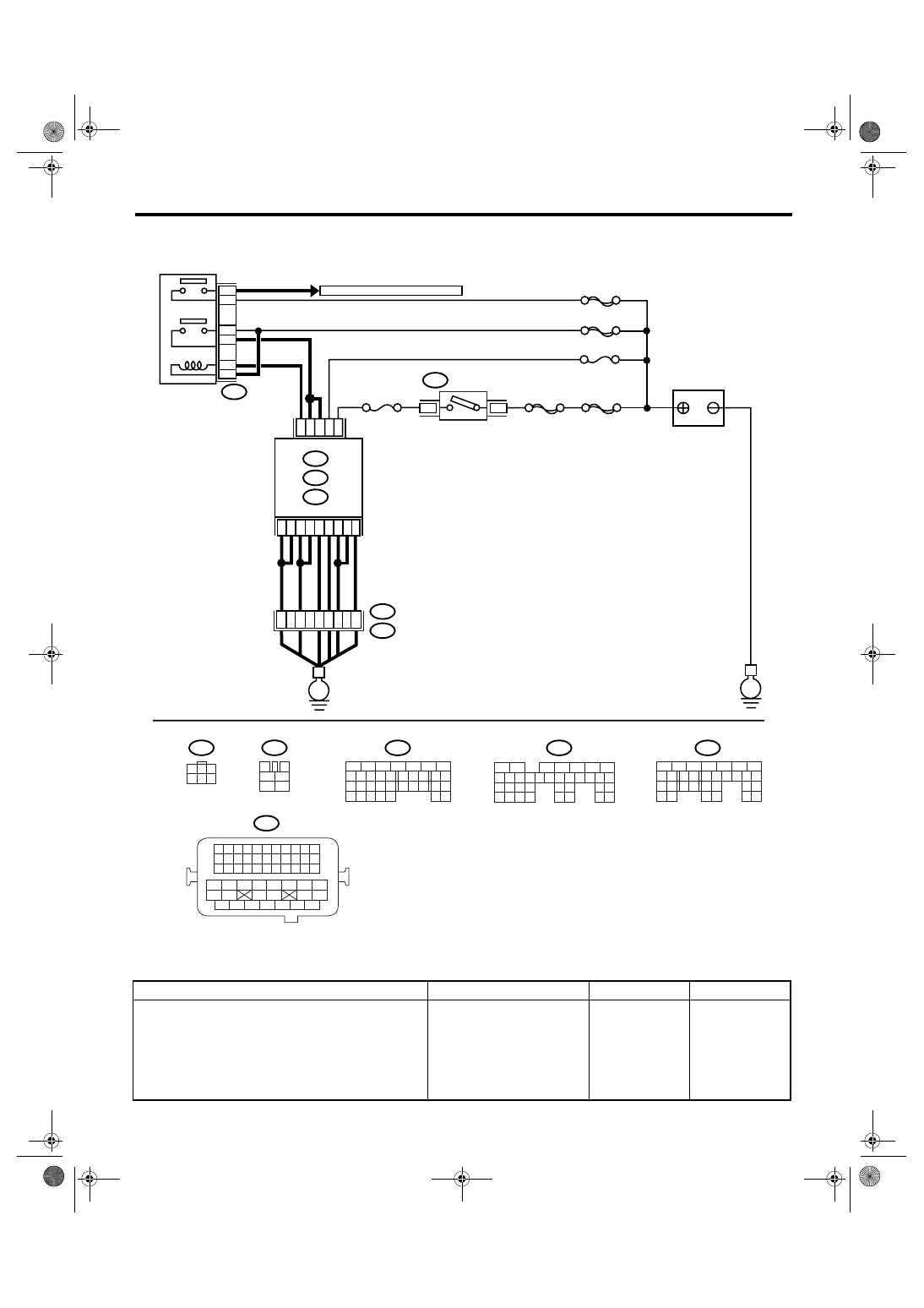
AW:DTC P0607 CONTROL MODULE PERFORMANCE
DTC DETECTING CONDITION:
Immediately at fault recognition
TROUBLE SYMPTOM:
• Erroneous idling
• Poor driving performance
CAUTION:
After repair or replacement of faulty parts, perform Clear Memory Mode <Ref. to EN(H4DOTC)(diag)-
37, OPERATION, Clear Memory Mode.> and Inspection Mode <Ref. to EN(H4DOTC)(diag)-30, PROCE-
DURE, Inspection Mode.>.
EN(H4DOTC)(diag)-156
ENGINE (DIAGNOSTICS)
Diagnostic Procedure with Diagnostic Trouble Code (DTC)
WIRING DIAGRAM:
Step
Check
Yes
No
1
CHECK INPUT VOLTAGE OF ECM.
1) Turn the ignition switch to ON.
2) Measure the voltage between ECM con-
nector and chassis ground.
Connector & terminal
(B135) No. 5 (+) — Chassis ground (
−
):
(B135) No. 6 (+) — Chassis ground (
−
):
Is the voltage 10 — 13 V?
Repair the open or
ground short cir-
cuit of power sup-
ply circuit.
EN-03519
B72
BATTERY
MAIN RELAY
SBF-6
MAIN SBF
SBF-7
No.13
SBF-5
B72
TO FRONT OXYGEN(A/F) SENSOR
D16
A6
A7
B1
B4
D7
B12
D1
D2
D3
B5
B6
B19
D14
No.12
B47
E2
B21
2
1
4
6
5
3
ECM
E
E
3
6
B134
B135
B137
A:
B:
D:
54
35
36
12
34
3
4
1
2
5
6
B47
B21
B134
A:
B137
D:
B135
B:
IGNITION
SWITCH
5
6
7
8
2
1
9
4
3
10
24
22 23
25
11 12 13 14 15
26 27
28
16 17
18 19 20 21
33 34
29
32
30 31
5
6
7
8
2
1
9
4
3
10
24
22 23
25
11 12 13 14 15
26 27
28
16 17 18 19
20 21
29 30 31
32 33
34 35
5
6
7
8
2
1
9
4
3
10
22 23
11 12 13 14 15
24 25
26
16 17
18 19 20 21
27
28 29
30 31
37
1
3
4 5 6
2
1 2 3 4
12 13 14 15
5 6 7 8
16 17 18 19
9 10 11
20 21 22
23 24 25 26 27 28 29 30 31 32 33
35
34
37
36
39
38
41
40
43
42
44
45
47
46
49
48
51
50
53
52
54
Нет комментариевНе стесняйтесь поделиться с нами вашим ценным мнением.
Текст