Subaru Legacy (2005 year). Service manual — part 349
EN(H4DOTC)(diag)-165
ENGINE (DIAGNOSTICS)
Diagnostic Procedure with Diagnostic Trouble Code (DTC)
Step
Check
Yes
No
1
CHECK ANY OTHER DTC ON DISPLAY.
Is any other DTC displayed?
Check DTC using
“List of Diagnostic
Trouble Code
(DTC)”. <Ref. to
EN(H4DOTC)(diag
)-62, List of Diag-
nostic Trouble
Code (DTC).>
2
CHECK HARNESS BETWEEN STARTER
RELAY AND ECM.
1) Disconnect the connectors from starter
relay and ECM.
2) Measure the resistance of harness
between ECM and chassis ground.
Connector & terminal
(B135) No. 32 — Chassis ground:
Is the resistance more than 1
M
Ω?
Repair the ground
short circuit
between starter
motor and ECM.
Repair the poor
contact in ECM
connector.
EN(H4DOTC)(diag)-166
ENGINE (DIAGNOSTICS)
Diagnostic Procedure with Diagnostic Trouble Code (DTC)
BD:DTC P1560 BACK-UP VOLTAGE CIRCUIT MALFUNCTION
DTC DETECTING CONDITION:
Immediately at fault recognition
CAUTION:
After repair or replacement of faulty parts, perform Clear Memory Mode <Ref. to EN(H4DOTC)(diag)-
37, OPERATION, Clear Memory Mode.> and Inspection Mode <Ref. to EN(H4DOTC)(diag)-30, PROCE-
DURE, Inspection Mode.>.
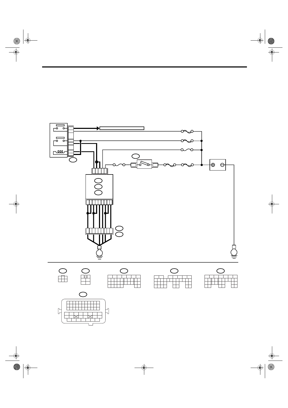
WIRING DIAGRAM:
EN-03519
B72
BATTERY
MAIN RELAY
SBF-6
MAIN SBF
SBF-7
No.13
SBF-5
B72
TO FRONT OXYGEN(A/F) SENSOR
D16
A6
A7
B1
B4
D7
B12
D1
D2
D3
B5
B6
B19
D14
No.12
B47
E2
B21
2
1
4
6
5
3
ECM
E
E
3
6
B134
B135
B137
A:
B:
D:
54
35
36
12
34
3
4
1
2
5
6
B47
B21
B134
A:
B137
D:
B135
B:
IGNITION
SWITCH
5
6
7
8
2
1
9
4
3
10
24
22 23
25
11 12 13 14 15
26 27
28
16 17
18 19 20 21
33 34
29
32
30 31
5
6
7
8
2
1
9
4
3
10
24
22 23
25
11 12 13 14 15
26 27
28
16 17 18 19
20 21
29 30 31
32 33
34 35
5
6
7
8
2
1
9
4
3
10
22 23
11 12 13 14 15
24 25
26
16 17
18 19 20 21
27
28 29
30 31
37
1
3
4 5 6
2
1 2 3 4
12 13 14 15
5 6 7 8
16 17 18 19
9 10 11
20 21 22
23 24 25 26 27 28 29 30 31 32 33
35
34
37
36
39
38
41
40
43
42
44
45
47
46
49
48
51
50
53
52
54
EN(H4DOTC)(diag)-167
ENGINE (DIAGNOSTICS)
Diagnostic Procedure with Diagnostic Trouble Code (DTC)
Step
Check
Yes
No
1
CHECK INPUT SIGNAL OF ECM.
1) Turn the ignition switch to OFF.
2) Measure the voltage between ECM and
chassis ground.
Connector & terminal
(B135) No. 19 (+) — Chassis ground (
−
):
Is the voltage more than 10 V? Repair the poor
contact in ECM
connector.
2
CHECK HARNESS BETWEEN ECM AND
MAIN FUSE BOX CONNECTOR.
1) Disconnect the connector from ECM.
2) Measure the resistance of harness
between ECM and chassis ground.
Connector & terminal
(B135) No. 19 — Chassis ground:
Is the resistance less than 10
Ω?
Repair the ground
short circuit of har-
ness between
ECM connector
and battery termi-
nal.
3
CHECK FUSE No. 13.
Is the fuse blown out?
Replace the fuse.
Repair the har-
ness and connec-
tor.
NOTE:
In this case, repair
the following:
• Open circuit of
harness between
ECM and battery
• Poor contact in
ECM connector
• Poor contact in
battery terminal
EN(H4DOTC)(diag)-168
ENGINE (DIAGNOSTICS)
Diagnostic Procedure with Diagnostic Trouble Code (DTC)
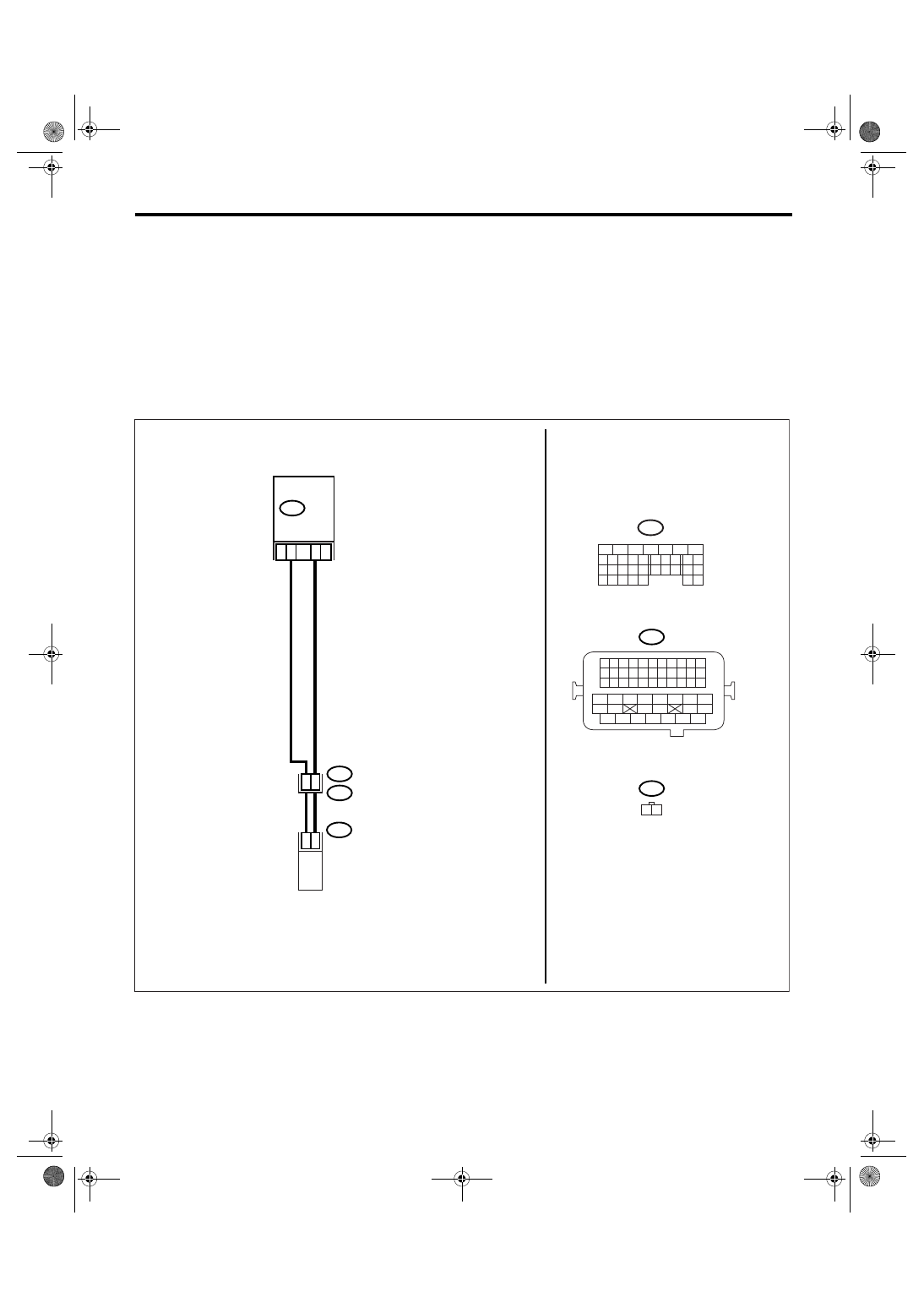
BE:DTC P2088 INTAKE CAMSHAFT POSITION ACTUATOR CONTROL CIRCUIT
LOW (BANK 1)
DTC DETECTING CONDITION:
Immediately at fault recognition
TROUBLE SYMPTOM:
Erroneous idling
CAUTION:
After repair or replacement of faulty parts, perform Clear Memory Mode <Ref. to EN(H4DOTC)(diag)-
37, OPERATION, Clear Memory Mode.> and Inspection Mode <Ref. to EN(H4DOTC)(diag)-30, PROCE-
DURE, Inspection Mode.>.
WIRING DIAGRAM:
EN-01960
B21
E2
B134
E38
28
2
1
24
23
E38
B21
1 2
18
B134
5
6
7
8
2
1
9
4
3
10
24
22 23
25
11 12 13 14 15
26 27
28
16 17
18 19 20 21
33 34
29
32
30 31
ECM
OIL FLOW CONTROL
SOLENOID VALVE RH
1 2 3 4
12 13 14 15
5 6 7 8
16 17 18 19
9 10 11
20 21 22
23 24 25 26 27 28 29 30 31 32 33
35
34
37
36
39
38
41
40
43
42
44
45
47
46
49
48
51
50
53
52
54
Нет комментариевНе стесняйтесь поделиться с нами вашим ценным мнением.
Текст