Subaru Legacy (2005 year). Service manual — part 754
ABS
ABS
Page
General Description . . . . . . . . . . . . . . . . . . . . . 2
ABS Control Module and Hydraulic Control Unit (ABSCM&H/U). . . . 6
ABS Sequence Control . . . . . . . . . . . . . . . . . . . .10
Front ABS Wheel Speed Sensor. . . . . . . . . . . . . . . ...13
Rear ABS Wheel Speed Sensor . . . . . . . . . . . . . . . ...15
Front Magnetic Encoder. . . . . . . . . . . . . . . . . . . 16
Rear Magnetic Encoder . . . . . . . . . . . . . . . . . . . 17
G Sensor . . . . . . . . . . . . . . . . . . . . . . . . ...18
ABS-2
ABS
General Description
1. General Description
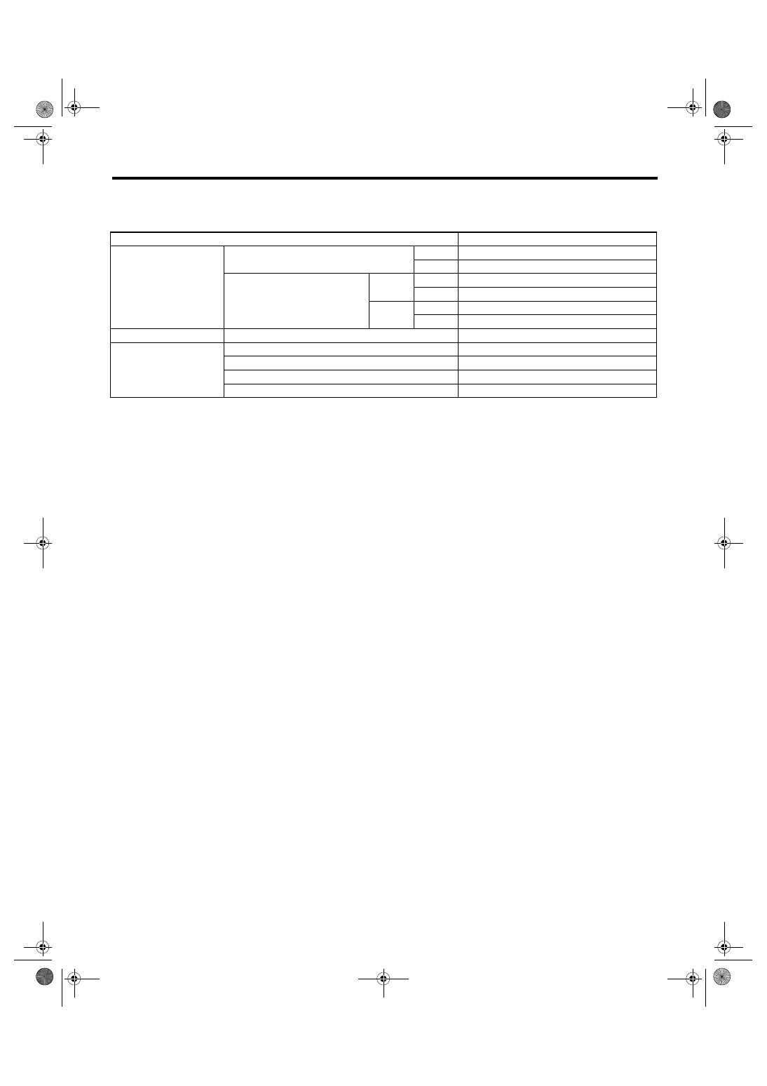
A: SPECIFICATION
Item
Specification or identification
ABS wheel speed sensor
ABS wheel speed sensor gap (for refer-
ence)
Front
0.77 — 1.43 mm (0.030 — 0.056 in)
Rear
0.64 — 1.56 mm (0.025 — 0.061 in)
Marks of harness (Marks, Color)
Front
RH
K1 (White)
LH
K2 (Yellow)
Rear
RH
K5 (White)
LH
K6 (Yellow)
G sensor
G sensor voltage
2.3
±0.2 V
ABSCM&H/U identifica-
tion
AT (Except for OUTBACK)
J1
MT (Except for OUTBACK)
J2
AT (OUTBACK)
J3
MT (OUTBACK)
J4
ABS-3
ABS
General Description
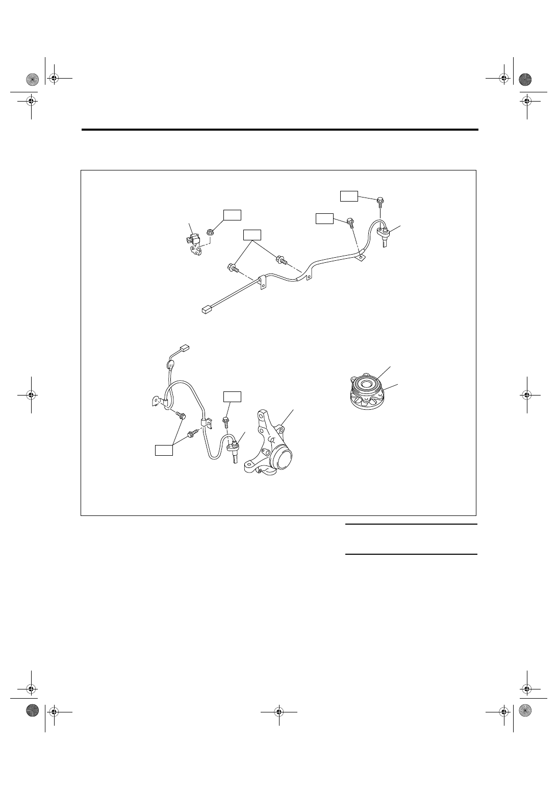
B: COMPONENT
1. ABS WHEEL SPEED SENSOR
(1)
G sensor
(4)
Rear ABS wheel speed sensor LH Tightening torque: N
⋅
m (kgf-m, ft-lb)
(2)
Front ABS wheel speed sensor LH
(5)
Hub unit bearing
T1: 7.5 (0.76, 5.5)
(3)
Front housing
(6)
Magnetic encoder
T2: 33 (3.4, 24.3)
T1
ABS00380
T2
T1
(1)
(5)
(4)
(3)
(2)
T2
T1
(6)
T2
ABS-4
ABS
General Description
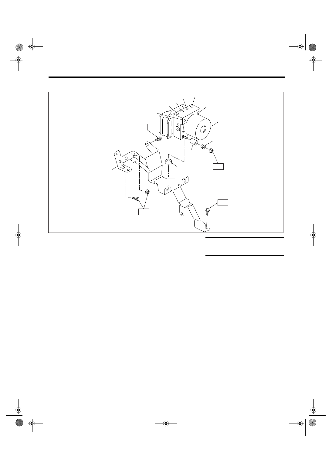
2. ABS CONTROL MODULE AND HYDRAULIC CONTROL UNIT (ABSCM&H/U)
C: CAUTION
• Wear work clothing, including a cap, protective
goggles and protective shoes during operation.
• Before disconnecting electrical connectors of
sensors or units, be sure to disconnect the ground
cable from battery.
• Before removal, installation or disassembly, be
sure to clarify the failure. Avoid unnecessary re-
moval, installation, disassembly and replacement.
• Be careful not to burn yourself, because each
part on the vehicle is hot after running.
• Be sure to tighten fasteners including bolts and
nuts to the specified torque.
• Place shop jacks or rigid racks at the specified
points.
(1)
ABS control module and hydraulic
control unit (ABSCM&H/U)
(6)
Primary inlet
Tightening torque: N
⋅
m (kgf-m, ft-lb)
(7)
Secondary inlet
T1: 7.5 (0.76, 5.5)
(2)
Front outlet RH
(8)
Damper
T2: 33 (3.4, 24.3)
(3)
Rear outlet LH
(9)
Spacer
(4)
Rear outlet RH
(10)
Damper
(5)
Front outlet LH
(11)
Bracket
ABS00381
(1)
(8)
(11)
(7)
(6)
(5)
(4)
(3)
(10)
(2)
T1
T2
T2
(9)
T2
Нет комментариевНе стесняйтесь поделиться с нами вашим ценным мнением.
Текст