Subaru Legacy (2005 year). Service manual — part 752
DS-23
DRIVE SHAFT SYSTEM
Front Drive Shaft
8) While depressing the brake pedal, tighten a new
axle nut (olive color) to the specified torque and
lock it securely.
Tightening torque:
220 N
⋅
m (22.4 kgf-m, 162 ft-lb)
CAUTION:
• Install the wheel after installation of the axle
nut. Failure to follow this rule may damage the
wheel bearing.
• Be sure to tighten axle nut to specified
torque. Do not overtighten it as this may dam-
age wheel bearing.
9) After tightening axle nut, lock it securely.
10) Add transmission gear oil. (MT model)
11) Add differential gear oil. (AT model)
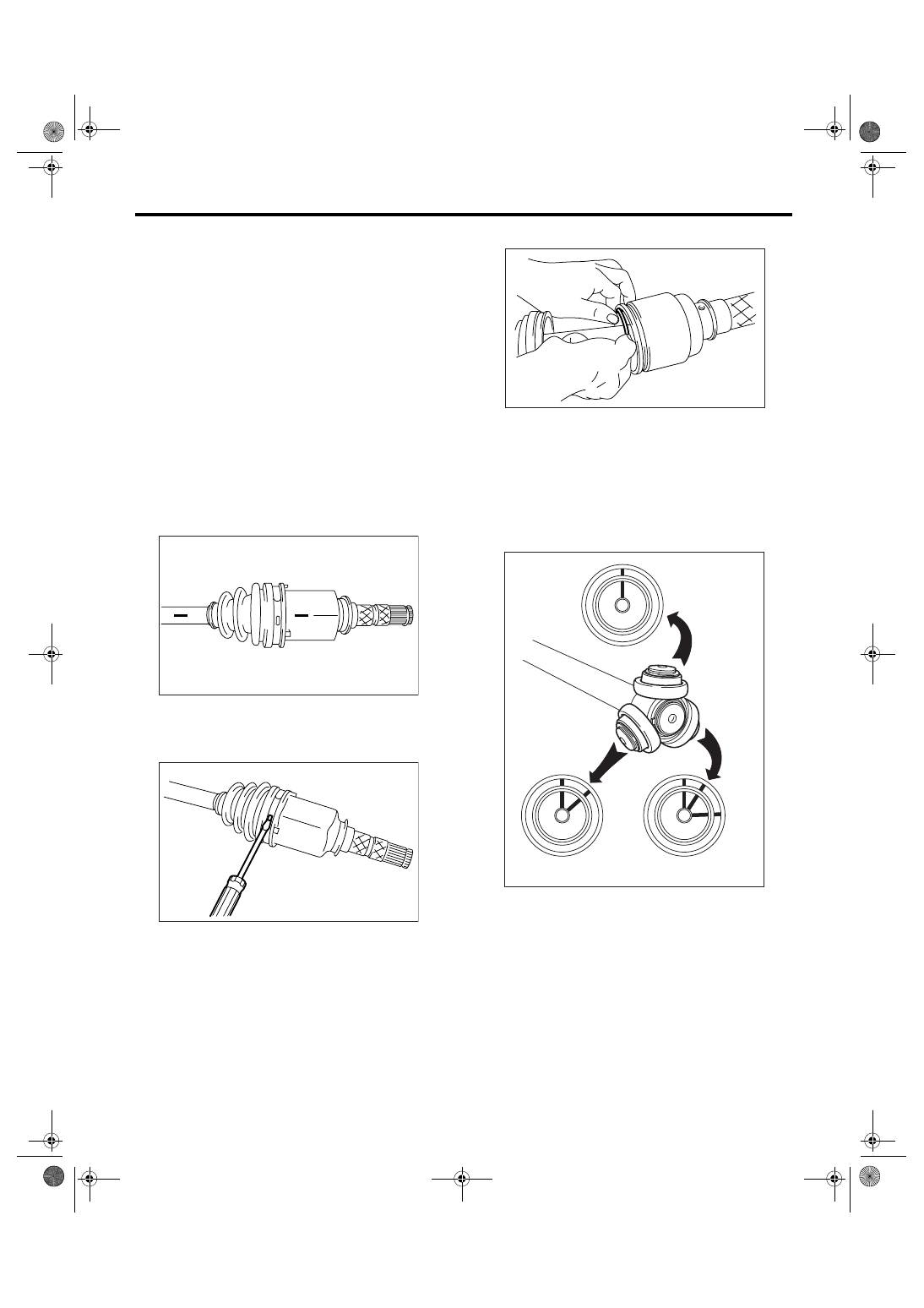
C: DISASSEMBLY
1) Place alignment marks on the shaft and outer
race.
2) Remove the PTJ boot band and boot.
CAUTION:
Be careful not to damage boot.
3) Remove the snap ring from PTJ outer race.
4) Remove the PTJ outer race from shaft assem-
bly.
5) Wipe off grease.
CAUTION:
The grease is a special grease. Do not confuse
with other greases.
6) Place alignment marks on the roller kit and trun-
nion.
7) Remove the roller kit from trunnion.
CAUTION:
Be careful with the roller kit position.
DS-00106
DS-00107
DS-00108
DS-00109
DS-24
DRIVE SHAFT SYSTEM
Front Drive Shaft
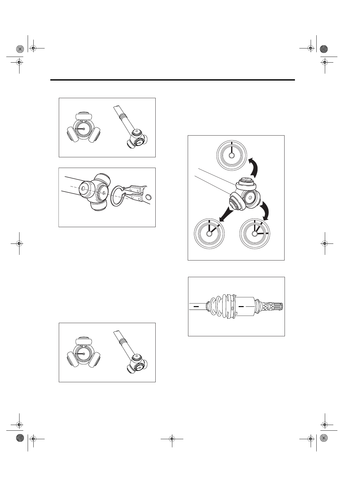
8) Place alignment marks on the trunnion and
shaft.
9) Remove the snap ring and trunnion.
CAUTION:
Be sure to wrap shaft splines with vinyl tape to
prevent boot from scratches.
10) Remove the PTJ boot.
NOTE:
Further disassembly of axle is impossible because
the EBJ cannot be disassembled.
D: ASSEMBLY
NOTE:
Use specified grease.
PTJ side: NSG301 (Part No. 28395AG020)
1) Place the PTJ boot at the center of shaft.
2) Align alignment marks and install the trunnion on
the shaft.
3) Install the snap ring to shaft.
CAUTION:
Confirm that the snap ring is completely fitted
in shaft groove.
4) Fill 100 to 110 g (3.53 to 3.88 oz.) of specified
grease into the interior of PTJ outer race.
5) Apply a thin coat of specified grease to the roller
kit and trunnion.
6) Align alignment marks on roller kit and trunnion
and install the roller kit.
CAUTION:
Be careful with the roller kit position.
7) Align alignment marks on the shaft and outer
race, and install outer race.
8) Install the snap ring in the groove on PTJ outer
race.
CAUTION:
Pull the shaft lightly and assure that the snap
ring is completely fitted in the groove.
9) Apply an even coat of the specified grease 30 to
40 g (1.06 to 1.41 oz.) to the entire inner surface of
boot.
10) Install the PTJ boot taking care not to twist it.
DS-00110
DS-00111
DS-00110
DS-00109
DS-00106
DS-25
DRIVE SHAFT SYSTEM
Front Drive Shaft
CAUTION:
• The large end of PTJ boot and the boot
groove shall be cleaned completely so as to be
free from grease and other substances.
• When installing PTJ boot, position outer race
of PTJ at center of its travel.
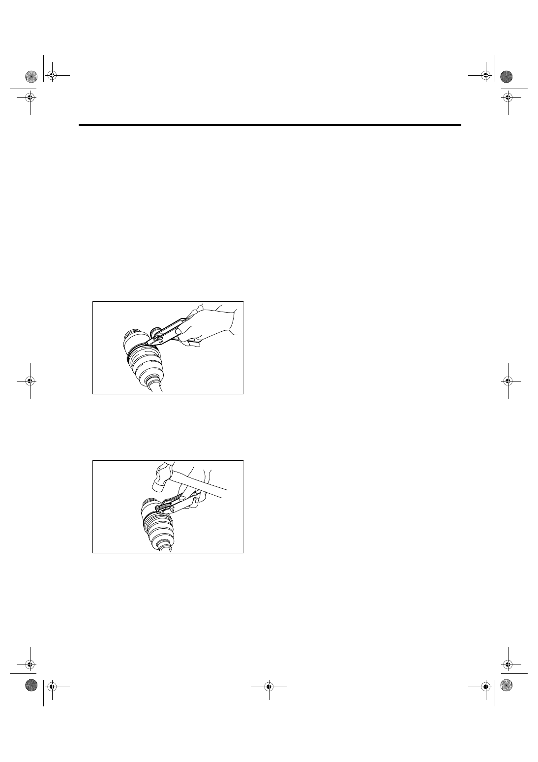
11) Put a new band through the clip and wind twice
in alignment with band groove of boot.
12) Pinch the end of band with pliers. Hold the clip
and tighten securely.
NOTE:
When tightening boot, use care so that the air with-
in the boot is appropriate.
13) Tighten the band using ST.
ST
925091000
BAND TIGHTENING TOOL
NOTE:
Tighten the band until it cannot be moved by hand.
14) Tap on the clip with the punch provided at the
end of ST.
ST
925091000
BAND TIGHTENING TOOL
CAUTION:
Tap to an extent that the boot underneath is not
damaged.
15) Cut off the band with an allowance of about 10
mm (0.39 in) left from the clip and bend this allow-
ance over the clip.
CAUTION:
Be careful so that the end of the band is in close
contact with clip.
16) Extend and retract the PTJ to provide equal
grease coating.
E: INSPECTION
Check the removed parts for damage, wear, corro-
sion etc. If faulty, repair or replace.
• PTJ (pillow tripod joint)
Check for seizure, corrosion, damage, wear and
excessive play.
• EBJ (high-efficiency compact ball fixed joint)
Check for seizure, corrosion, damage and exces-
sive play.
• Shaft
Check for excessive bending, twisting, damage
and wear.
• Boot
Check for wear, warping, breakage and scratches.
• Grease
Check for discoloration and fluidity.
DS-00132
DS-00133
DS-26
DRIVE SHAFT SYSTEM
Rear Drive Shaft
7. Rear Drive Shaft
A: REMOVAL
1) Disconnect the ground cable from battery.
2) Lift-up the vehicle, and then remove the rear
wheels.
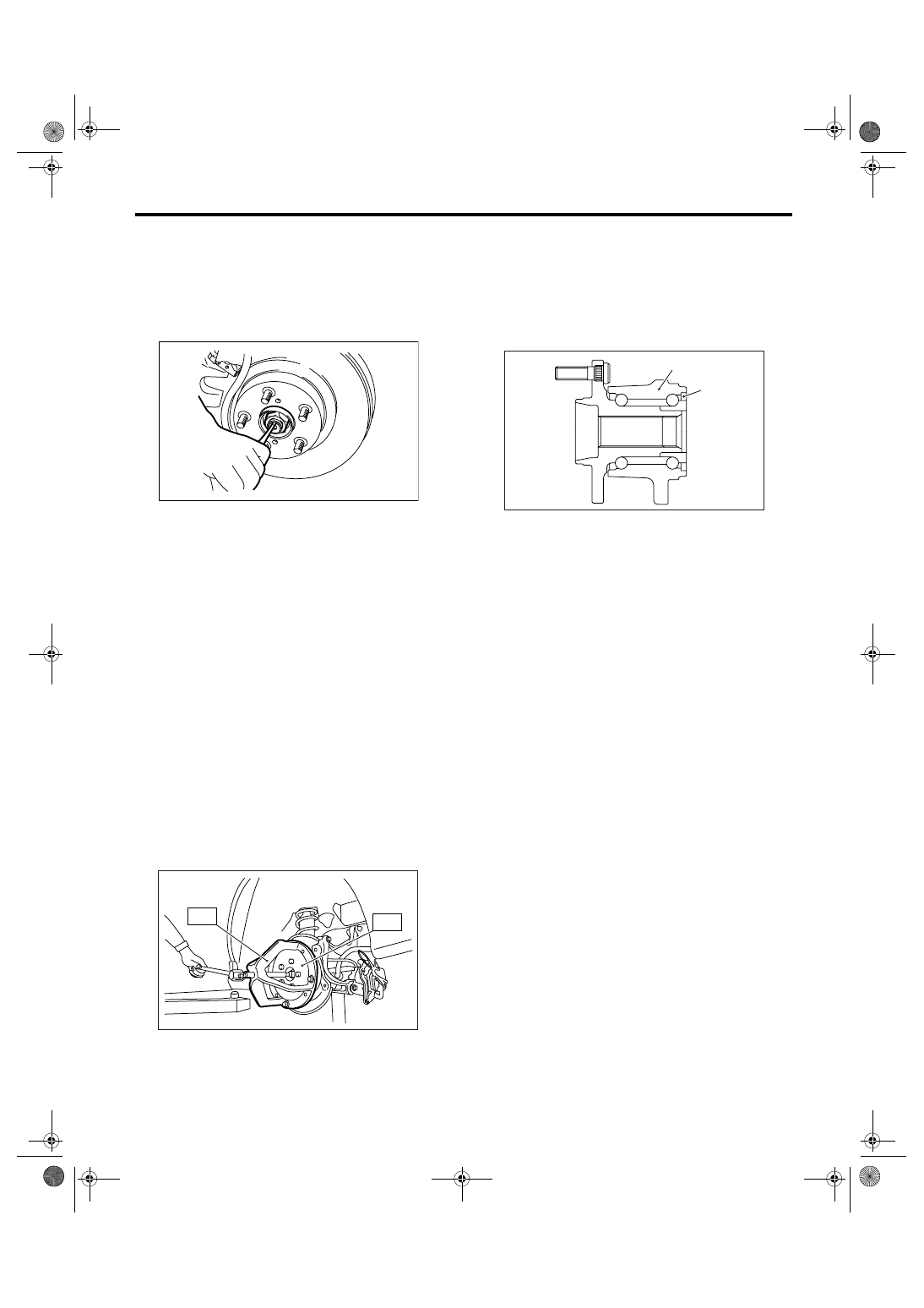
3) Unlock the axle nut.
4) While applying the parking brake, remove the
axle nut using the socket wrench.
CAUTION:
Remove the wheel before loosening the axle
nut. Failure to follow this rule may damage the
wheel bearings.
5) Remove the rear differential assembly.
• T-type
<Ref. to DI-29, REMOVAL, Rear Differential (T-
type).>
• VA-type
<Ref. to DI-46, REMOVAL, Rear Differential (VA-
type).>
6) Remove the axle nut and rear drive shaft. If it is
hard to remove, use ST1 and ST2.
ST1
926470000
AXLE SHAFT PULLER
ST2
927140000
AXLE SHAFT PULLER
PLATE
CAUTION:
• Do not hammer drive shaft when removing.
• Do not damage the oil seal and magnetic en-
coder.
B: INSTALLATION
1) Insert the BJ or EBJ into rear hub splines.
CAUTION:
• Be careful not to damage the magnetic en-
coder.
• Do not get closer the tool which charged
magnetism to magnetic encorder.
2) Draw the rear drive shaft into specified position.
CAUTION:
Do not hammer drive shaft when installing it.
3) Tighten the axle nut temporarily.
4) Install the rear differential assembly.
• T-type
<Ref. to DI-30, INSTALLATION, Rear Differential
(T-type).>
• VA-type
<Ref. to DI-47, INSTALLATION, Rear Differential
(VA-type).>
5) While applying the parking brake and depress-
ing the brake pedal, tighten a new axle nut (olive
color) to specified torque and lock it securely.
Tightening torque:
190 N
⋅
m (19.4 kgf-m, 140 ft-lb)
CAUTION:
• Install the wheel after installation of the axle
nut. Failure to follow this rule may damage the
wheel bearing.
• Be sure to tighten the axle nut to specified
torque. Do not overtighten it as this may dam-
age wheel bearing.
DS-00038
DS-00122
ST2
ST1
(1) Magnetic encoder
(2) Rear hub unit bearing
DS-00251
(2)
(1)
Нет комментариевНе стесняйтесь поделиться с нами вашим ценным мнением.
Текст