Subaru Legacy (2005 year). Service manual — part 753
DS-27
DRIVE SHAFT SYSTEM
Rear Drive Shaft
6) Lock the axle nut securely.
7) Install the wheel.
Tightening torque:
90 N
⋅
m (9.2 kgf-m, 66 ft-lb)
C: DISASSEMBLY
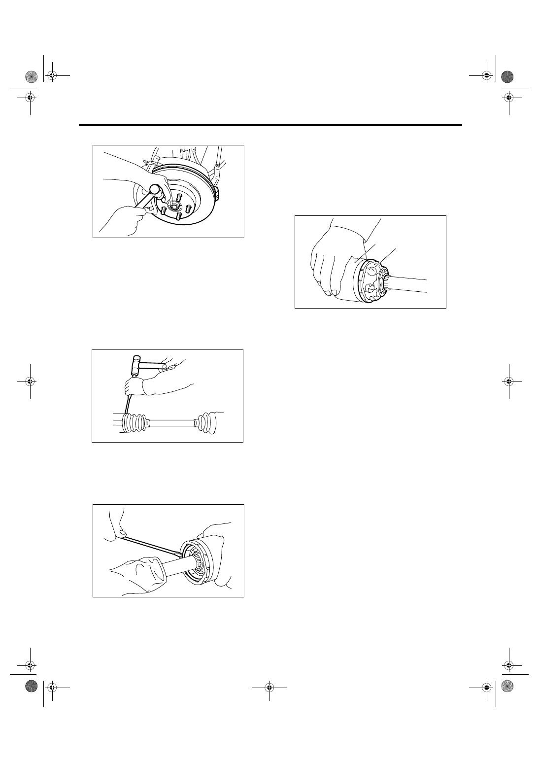
1) Straighten the bent claw of larger end of DOJ
boot.
2) Loosen the band by means of screwdriver or pli-
ers.
CAUTION:
Be careful not to damage boot.
3) Remove the boot band on the small end of DOJ
boot in the same manner.
4) Remove the larger end of DOJ boot from DOJ
outer race.
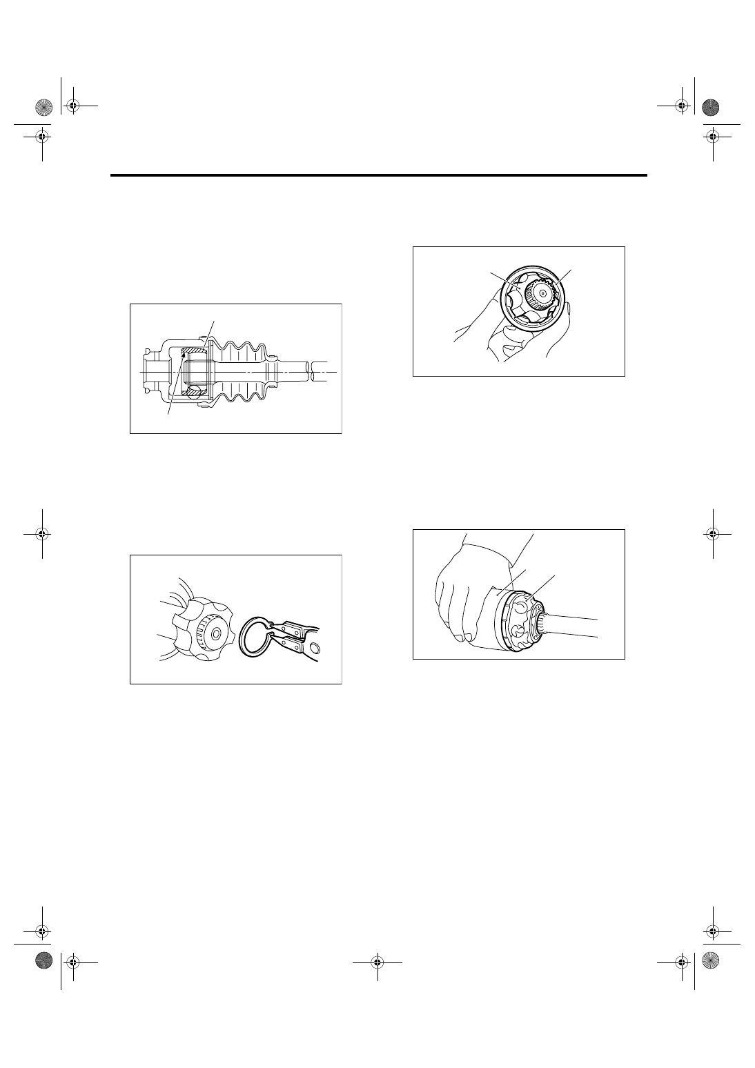
5) Pry and remove the round circlip located at the
neck of DOJ outer race with a screwdriver.
6) Take out the DOJ outer race from shaft assem-
bly.
7) Wipe off the grease and take out balls.
CAUTION:
The grease is a special grease (grease for con-
stant velocity joint). Do not confuse with other
greases.
NOTE:
Disassemble exercising care not to lose balls (6
pcs).
8) To remove the cage from inner race, turn the
cage by a half pitch to the track groove of inner race
and shift the cage.
9) Remove the snap ring, which fixes inner race to
shaft, using pliers.
10) Take out the DOJ inner race.
11) Take off the DOJ cage from shaft and remove
DOJ boot.
CAUTION:
Be sure to wrap shaft splines with vinyl tape to
prevent boot from scratches.
12) Remove the BJ boot or EBJ boot in the same
procedure as DOJ boot.
NOTE:
Further disassembly of axle is impossible because
the BJ and EBJ cannot be disassembled.
D: ASSEMBLY
NOTE:
Use specified grease.
BJ side:
NTG2218-M (Part No. 28395AG010)
EBJ side:
NTG2218-M (Part No. 28395AG010)
DOJ side:
NKG205 (Part No. 28495AG000)
1) Install the BJ or EBJ boot in specified position,
and fill it with 60 to 70 g (2.12 to 2.47 oz.) of speci-
fied grease.
DS-00048
DS-00124
DS-00125
(A) Outer race
(B) Grease
DS-00126
(B)
(A)
DS-28
DRIVE SHAFT SYSTEM
Rear Drive Shaft
2) Place the DOJ boot at the center of shaft.
CAUTION:
Be sure to wrap shaft splines with vinyl tape to
prevent boot from scratches.
3) Insert the DOJ cage onto shaft.
NOTE:
Insert the cage with the cut-out portion facing the
shaft end, since the cage has an orientation.
4) Install the DOJ inner race on shaft and fit the
snap ring with pliers.
NOTE:
Confirm that the snap ring is completely fitted in the
shaft groove.
5) Install the cage to inner race fixed upon shaft.
NOTE:
Fit the cage with the protruded part aligned with the
track on the inner race and then turn by a half pitch.
6) Fill 80 to 90 g (2.82 to 3.17 oz.) of specified
grease into the interior of DOJ outer race.
7) Apply a coat of specified grease to the cage
pocket and six balls.
8) Insert six balls into the cage pocket.
9) Align the outer race track and ball positions, and
place the shaft, inner race, cage and balls in the
original positions and then fit outer race.
10) Install the snap ring in the groove on DOJ outer
race.
NOTE:
• Assure that the balls, cage and inner race are
completely fitted in the outer race of DOJ.
• Use care not to place the matched position of
snap ring in the ball groove of outer race.
(A) Cage
(B) Cutout
DS-00127
(B)
(A)
DS-00128
(A) Inner race
(B) Cage
(A) Outer race
(B) Grease
(B)
(A)
DS-00129
DS-00126
(B)
(A)
DS-29
DRIVE SHAFT SYSTEM
Rear Drive Shaft
• Pull the shaft lightly and assure that the circlip is
completely fitted in the groove.
11) Apply an even coat of the specified grease [20
to 30 g (0.71 to 1.06 oz.)] to the entire inner surface
of boot. Also apply grease to shaft.
12) Install the DOJ boot taking care not to twist it.
NOTE:
• The inside of the larger end of DOJ boot and the
boot groove shall be cleaned so as to be free from
grease and other substances.
• When installing DOJ boot, position outer race of
DOJ at center of its travel.
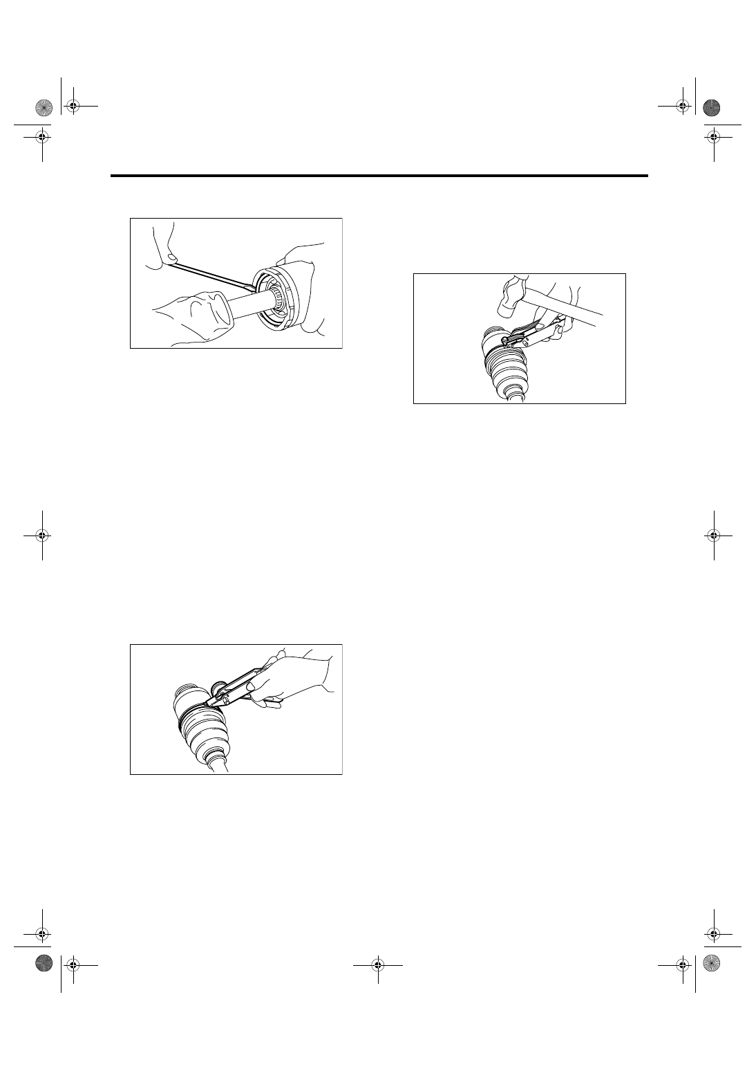
13) Put a new band through the clip and wind twice
in alignment with band groove of boot.
14) Pinch the end of band with pliers. Hold the clip
and tighten securely.
NOTE:
When tightening boot, exercise care so that the air
within the boot is appropriate.
15) Tighten the band by using ST.
ST
925091000
BAND TIGHTENING TOOL
NOTE:
Tighten the band until it cannot be moved by hand.
16) Tap on the clip with the punch provided at the
end of ST.
ST
925091000
BAND TIGHTENING TOOL
NOTE:
Tap to an extent that the boot underneath is not
damaged.
17) Cut off the band with an allowance of about 10
mm (0.39 in) left from the clip and bend this allow-
ance over the clip.
NOTE:
Be careful so that the end of the band is in close
contact with clip.
18) Install the BJ boot or EBJ boot in the same pro-
cedure as DOJ boot.
19) Extend and retract the DOJ to provide equal
grease coating.
E: INSPECTION
Check the removed parts for damage, wear, corro-
sion etc. Repair or replace if defective.
• DOJ (Double Offset Joint)
Check for seizure, corrosion, damage, wear and
excessive play.
• EBJ (high-efficiency compact ball fixed joint)
Check for seizure, corrosion, damage, wear and
excessive play.
• Shaft
Check for excessive bending, twisting, damage
and wear.
• BJ (Bell Joint)
Check for seizure, corrosion, damage and exces-
sive play.
• Boot
Check for wear, warping, breakage and scratches.
• Grease
Check for discoloration and fluidity.
DS-00125
DS-00132
DS-00133
DS-30
DRIVE SHAFT SYSTEM
General Diagnostic Table
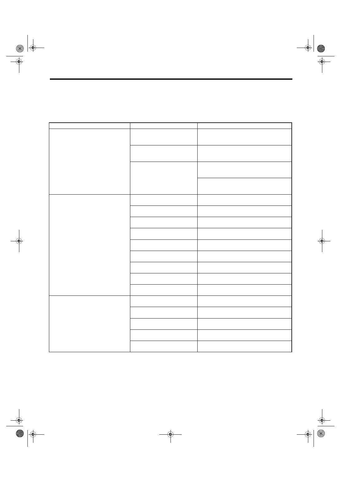
8. General Diagnostic Table
A: INSPECTION
NOTE:
Vibration while cruising may be caused by an unbalanced tire, improper tire inflation pressure, improper
wheel alignment, etc.
Symptom
Possible cause
Corrective action
Noise or vibration from propeller shaft
Center bearing
Check the center bearing. <Ref. to DS-12, CEN-
TER BEARING FREE PLAY, INSPECTION, Pro-
peller Shaft.>
Runout of propeller shaft
Check the vibration of propeller shaft. <Ref. to
DS-11, RUNOUT OF PROPELLER SHAFT,
INSPECTION, Propeller Shaft.>
Loose or free play of connection
Check joint and connector. <Ref. to DS-11,
JOINTS AND CONNECTIONS, INSPECTION,
Propeller Shaft.>
Check splines and bearing. <Ref. to DS-11,
SPLINES AND BEARING, INSPECTION, Pro-
peller Shaft.>
Abnormal wheel vibration
Wheel is out of balance.
Check the wheel balance. <Ref. to WT-7,
ADJUSTMENT, Wheel Balancing.>
Front wheel alignment
Check the front wheel alignment. <Ref. to FS-7,
INSPECTION, Wheel Alignment.>
Rear wheel alignment
Check the rear wheel alignment. <Ref. to RS-8,
INSPECTION, Wheel Alignment.>
Front strut
Check the front strut. <Ref. to FS-23, INSPEC-
TION, Front Strut.>
Rear shock absorber
Check the rear shock absorber. <Ref. to RS-16,
INSPECTION, Rear Shock Absorber.>
Front drive shaft
Check the front drive shaft. <Ref. to DS-25,
INSPECTION, Front Drive Shaft.>
Rear drive shaft
Check the rear drive shaft. <Ref. to DS-29,
INSPECTION, Rear Drive Shaft.>
Front hub unit bearing
Check the front hub unit bearing. <Ref. to DS-18,
INSPECTION, Front Hub Unit Bearing.>
Rear hub unit bearing
Check the rear hub unit bearing. <Ref. to DS-21,
INSPECTION, Rear Hub Unit Bearing.>
Noise from the underbody
Wheel is out of balance.
Check the wheel balance. <Ref. to WT-7,
ADJUSTMENT, Wheel Balancing.>
Front wheel alignment
Check the front wheel alignment. <Ref. to FS-7,
INSPECTION, Wheel Alignment.>
Rear wheel alignment
Check the rear wheel alignment. <Ref. to RS-8,
INSPECTION, Wheel Alignment.>
Front strut
Check the front strut. <Ref. to FS-23, INSPEC-
TION, Front Strut.>
Rear shock absorber
Check the rear shock absorber. <Ref. to RS-16,
INSPECTION, Rear Shock Absorber.>
Нет комментариевНе стесняйтесь поделиться с нами вашим ценным мнением.
Текст