Subaru Legacy (2005 year). Service manual — part 633
5AT(diag)-123
AUTOMATIC TRANSMISSION (DIAGNOSTICS)
Diagnostic Procedure with Diagnostic Trouble Code (DTC)
AQ:DTC P1798 GEAR 1 ENGINE BRAKE
NOTE:
Refer to DTC P0773 for diagnostic procedure. <Ref. to 5AT(diag)-85, DTC P0773 SHIFT SOLENOID “E”
ELECTRICAL, Diagnostic Procedure with Diagnostic Trouble Code (DTC).>
15
CHECK INPUT VOLTAGE OF LATERAL G
SENSOR.
1) Turn the ignition switch to OFF.
2) Remove the console box.
3) Remove the lateral G sensor from vehicle.
(Do not disconnect connector.)
4) Turn the ignition switch to ON.
5) Measure the voltage between lateral G
sensor connector terminals.
Connector & terminal
(B359) No. 1 (+) — No. 2 (
−
):
Is the voltage 4.75 — 5.25 V?
Repair the har-
ness connector
between lateral G
sensor and TCM.
16
CHECK OPEN CIRCUIT IN LATERAL G SEN-
SOR OUTPUT HARNESS AND GROUND
HARNESS.
1) Turn the ignition switch to OFF.
2) Disconnect the connector from TCM.
3) Measure the resistance between TCM con-
nector terminals.
Connector & terminal
(B55) No. 5 — No. 6:
Is the resistance 5.0 — 5.6
k
Ω?
Repair the har-
ness connector
between lateral G
sensor and TCM.
17
CHECK LATERAL G SENSOR.
1) Connect the connector to lateral G sensor.
2) Connect the connector to the TCM.
3) Turn the ignition switch to ON.
4) Measure the voltage between lateral G
sensor connector terminals.
Connector & terminal
(B359) No. 3 (+) — No. 2 (
−
):
Is the voltage between 2.3 and
2.7 V when lateral G sensor is
horizontal?
Replace the lat-
eral G sensor.
<Ref. to 5AT-62,
Lateral G Sensor.>
18
CHECK LATERAL G SENSOR.
Measure the voltage between lateral G sensor
connector terminals.
Connector & terminal
(B359) No. 3 (+) — No. 2 (
−
):
Is the voltage between 3.3 —
4.3 V when lateral G sensor is
inclined to the right to 90
°?
Replace the lat-
eral G sensor.
<Ref. to 5AT-62,
Lateral G Sensor.>
19
CHECK LATERAL G SENSOR.
Measure the voltage between lateral G sensor
connector terminals.
Connector & terminal
(B359) No. 3 (+) — No. 2 (
−
):
Is the voltage 0.7 — 1.7 V
when lateral G sensor is
inclined to the left to 90
°?
Replace the lat-
eral G sensor.
<Ref. to 5AT-62,
Lateral G Sensor.>
20
CHECK POOR CONTACT IN CONNECTOR.
Turn the ignition switch to OFF.
Is there poor contact in con-
nector between TCM and lat-
eral G sensor?
Repair the con-
nector.
21
CHECK ABSCM&H/U.
1) Connect all the connectors.
2) Perform the clear memory mode.
3) Perform the inspection mode.
4) Read the DTC.
Is the same DTC displayed?
Replace the TCM.
<Ref. to 5AT-61,
Transmission Con-
trol Module
(TCM).>
22
CHECK OTHER DTC DETECTION.
Is any other DTC displayed?
Perform the diag-
nosis according to
DTC.
Temporary poor
contact occurs.
Step
Check
Yes
No
5AT(diag)-124
AUTOMATIC TRANSMISSION (DIAGNOSTICS)
Diagnostic Procedure with Diagnostic Trouble Code (DTC)
AR:DTC P1799 INTERLOCK
DTC DETECTING CONDITION:
Perform the interlock judgment when the oil pressure switch pattern detects the specified interlock patterns
other than shifting.
TROUBLE SYMPTOM:
Locked to 2nd, 4th or 5th gear depending on the vehicle condition at the time of diagnosis.
Step
Check
Yes
No
1
CHECK DTC OF TCM.
Is any of the DTC P0751,
P0756, P0761, P0766, P0771
displayed at the same time
with P1799?
Perform the diag-
nosis according to
DTC.
2
CHECK DTC P0756, P0766.
Perform the diagnosis accord-
ing to DTC P0756, P0766. Is
any malfunction detected?
Perform the diag-
nosis according to
DTC.
3
DRIVING CHECK.
1) Turn the ignition switch to OFF.
2) Perform the inspection mode.
Is DTC displayed?
Replace the trans-
mission assembly.
Temporary poor
contact occurs.
Check that the
harness connec-
tor has no faulty.
5AT(diag)-125
AUTOMATIC TRANSMISSION (DIAGNOSTICS)
Diagnostic Procedure with Diagnostic Trouble Code (DTC)
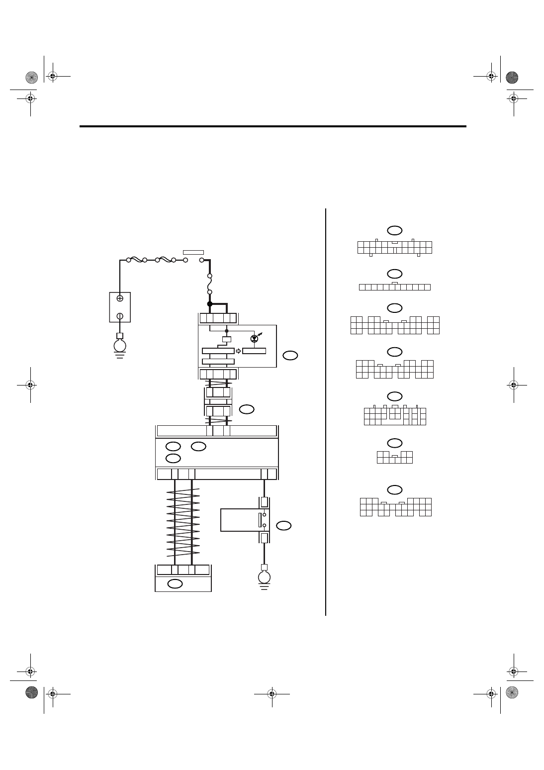
AS:DTC P1817 SPORT MODE SWITCH CIRCUIT (MANUAL SWITCH)
DTC DETECTING CONDITION:
Input signal circuit of SPORT mode and manual mode switch is open or shorted.
TROUBLE SYMPTOM:
• Manual mode can not be set.
• “SPORT” light illuminates when shifting to “N”
→ “D” range.
WIRING DIAGRAM:
i10
i77
i84
B280
B54
B116
B281
2
1
3 4
6 7 8 9 10
22
21
20
19
18
17
16
15
14
13
12
11
5
12
11
10
9
8
7
6
5
4
3
2
1
10
9
8
7
6
5
4
3
2
1
8
7
6
5
4
3
2
1
22 23
21
20
19
16
15
14
13
12
11
10
9
34 35
33
32
17
30
18
31
29
28
27
26
25
24
8
7
6
5
4
3
2
1
22
23
21
20
19
16
15
14
13
12
11
10
9
17
30
18
29
28
27
26
25
24
8
7
6
5
4
3
2
1
22 23
21
20
19
16
15
14
13
12
11
10
9
17 18
28
27
26
25
24
AT-03176
C26
B116
8
7
3
4
21
1
22
7
i10
i77
i84
A:
B280
B:
B281
C:
2
8
A26
A27
B20
B30
4
3
TCM
B54
SPORT
MAIN SBF
SBF-6
No.5
E
E
B
A
TTER
Y
IGNITION
SWITCH
COMBINATION
METER
JOINT
CONNECTOR
BODY INTEGRATED MODULE
SELECT
LEVER
SPORT MODE
AND MANUAL
MODE SWITCH
A:
B:
C:
1 2
7
8
9
5 6
3 4
10 11 12
19 20 21
13
14 15
16
17
18
22
23
24
5AT(diag)-126
AUTOMATIC TRANSMISSION (DIAGNOSTICS)
Diagnostic Procedure with Diagnostic Trouble Code (DTC)
Step
Check
Yes
No
1
CHECK BODY INTEGRATED MODULE.
1) Connect the Subaru Select Monitor to data
link connector.
2) Turn the ignition switch to ON. (engine
OFF)
3) Read the DTC of body integrated module
using Subaru Select Monitor. <Ref. to
LAN(diag)-14, OPERATION, Subaru Select
Monitor.>
Is DTC displayed?
Perform the diag-
nosis according to
DTC.
2
CHECK BODY INTEGRATED MODULE IN-
PUT SIGNAL.
1) Shift the select lever to “P” range.
2) Read the TIP mode SW data of body inte-
grated module using Subaru Select Monitor.
<Ref. to LAN(diag)-14, OPERATION, Subaru
Select Monitor.>
Is OFF displayed?
3
CHECK BODY INTEGRATED MODULE IN-
PUT SIGNAL.
1) Shift the select lever from “P” to “D” range.
2) Read the TIP mode SW data of body inte-
grated module using Subaru Select Monitor.
<Ref. to LAN(diag)-14, OPERATION, Subaru
Select Monitor.>
Is the indication on each range
OFF?
Replace the select
lever assembly.
<Ref. to CS-22,
Select Lever.>
4
CHECK BODY INTEGRATED MODULE IN-
PUT SIGNAL.
1) Shift the select lever to manual mode.
2) Shift the select lever to other than “D”
range.
3) Read the TIP mode SW data of body inte-
grated module using Subaru Select Monitor.
<Ref. to LAN(diag)-14, OPERATION, Subaru
Select Monitor.>
Is OFF displayed?
Replace the select
lever assembly.
<Ref. to CS-22,
Select Lever.>
5
CHECK DTC OF TCM.
Is DTC of Transmission Range
Sensor Circuit (PRNDL Input)
and AT CAN communication
circuit displayed?
Perform the diag-
nosis according to
each DTC.
6
CHECK TCM INPUT SIGNAL.
1) Shift the select lever from “P” to “D” range.
2) Read the TIP mode SW data of TCM using
Subaru Select Monitor. <Ref. to 5AT(diag)-17,
OPERATION, Subaru Select Monitor.>
Is the indication on each range
OFF?
Even if the SPORT
indicator lights
blinks, the system
is in normal condi-
tion. A temporary
poor contact of
connector or har-
ness may be the
cause.
Replace the TCM.
<Ref. to 5AT-61,
Transmission Con-
trol Module
(TCM).>
7
CHECK HARNESS BETWEEN BODY INTE-
GRATED MODULE AND SWITCH FOR
SPORT MODE AND MANUAL MODE.
1) Turn the ignition switch to OFF.
2) Disconnect harness connector from body
integrated module and select lever.
3) Measure the harness resistance between
body integrated module and chassis ground.
Connector & terminal
(B281) No. 26 — Chassis ground:
Is the resistance more than 1
M
Ω?
Repair the short
circuit of harness
between body inte-
grated module and
switch for SPORT
mode and manual
mode.
Нет комментариевНе стесняйтесь поделиться с нами вашим ценным мнением.
Текст