Subaru Legacy (2005 year). Service manual — part 634
5AT(diag)-127
AUTOMATIC TRANSMISSION (DIAGNOSTICS)
Diagnostic Procedure with Diagnostic Trouble Code (DTC)
AT:DTC P1840 TRANSMISSION FLUID PRESSURE SENSOR/SWITCH A CIR-
CUIT
DTC DETECTING CONDITION:
Front brake oil pressure switch malfunction
TROUBLE SYMPTOM:
Excessive shift shock
NOTE:
Refer to DTC P0751 for diagnostic procedure. <Ref. to 5AT(diag)-62, DTC P0751 SHIFT SOLENOID “A”
PERFORMANCE OR STUCK OFF, Diagnostic Procedure with Diagnostic Trouble Code (DTC).>
AU:DTC P1842 TRANSMISSION FLUID PRESSURE SENSOR/SWITCH C CIR-
CUIT
DTC DETECTING CONDITION:
Input clutch oil pressure switch malfunction
TROUBLE SYMPTOM:
Excessive shift shock
NOTE:
Refer to DTC P0756 for diagnostic procedure. <Ref. to 5AT(diag)-67, DTC P0756 SHIFT SOLENOID “B”
PERFORMANCE OR STUCK OFF, Diagnostic Procedure with Diagnostic Trouble Code (DTC).>
AV:DTC P1843 TRANSMISSION FLUID PRESSURE SENSOR/SWITCH D CIR-
CUIT
DTC DETECTING CONDITION:
Direct clutch oil pressure switch malfunction.
TROUBLE SYMPTOM:
Excessive shift shock
NOTE:
Refer to DTC P0766 for diagnostic procedure. <Ref. to 5AT(diag)-77, DTC P0766 SHIFT SOLENOID “D”
PERFORMANCE OR STUCK OFF, Diagnostic Procedure with Diagnostic Trouble Code (DTC).>
AW:DTC P1844 TRANSMISSION FLUID PRESSURE SENSOR/SWITCH E CIR-
CUIT
DTC DETECTING CONDITION:
High & low reverse clutch oil pressure switch malfunction.
TROUBLE SYMPTOM:
Excessive shift shock
NOTE:
Refer to DTC P0761 for diagnostic procedure. <Ref. to 5AT(diag)-72, DTC P0761 SHIFT SOLENOID “C”
PERFORMANCE OR STUCK OFF, Diagnostic Procedure with Diagnostic Trouble Code (DTC).>
8
CHECK SWITCH FOR SPORT MODE AND
MANUAL MODE.
1) Shift the select lever to “P” range.
2) Measure the resistance between harness
connector terminals of switch for SPORT mode
and manual mode.
Terminal
(B116) No. 7 — No. 8
Is the resistance more than 1
M
Ω?
Check the body
integrated module.
Replace the select
lever assembly.
<Ref. to CS-22,
Select Lever.>
Step
Check
Yes
No
5AT(diag)-128
AUTOMATIC TRANSMISSION (DIAGNOSTICS)
Diagnostic Procedure without Diagnostic Trouble Code (DTC)
15.Diagnostic Procedure without Diagnostic Trouble Code (DTC)
A: CHECK MANUAL MODE SWITCH
DIAGNOSIS:
Input signal circuit of manual mode switch is open or shorted.
TROUBLE SYMPTOM:
Does not shift on manual mode.
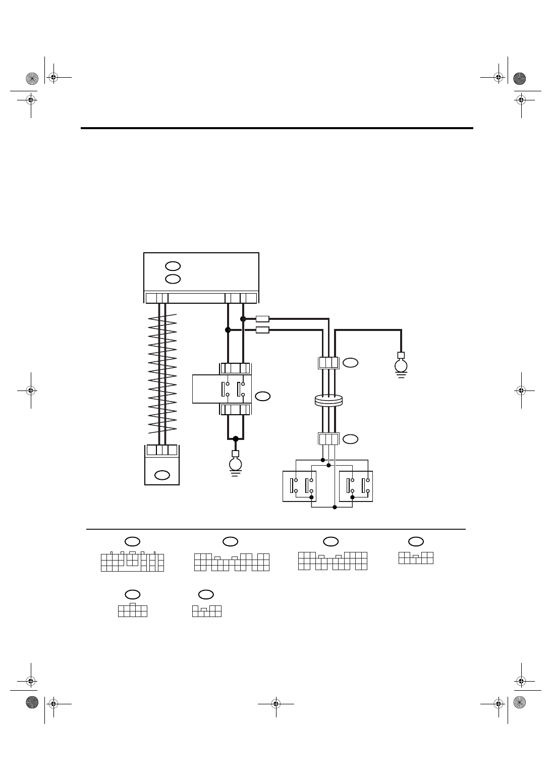
WIRING DIAGRAM:
AT-03197
B54
TCM
4
3
A20
A30
5
9
6
10
B15
B25
E
B68
2
7
8
E
4
2
3
ST4
BODY INTEGRATED MODULE
B280
B281
B:
A:
SELECT
LEVER
B116
ROLL CONNECTOR
LH
RH
STEERING SHIFT SWITCH
B54
1 2
7
8
9
5 6
3 4
10 11 12
19 20 21
13
14 15
16
17
18
22
23
24
B280
5
4
6 7
8
2
1
9
3
10
22
23
11 12 13 14 15
24 25
26 27
16 17 18
28 29
19 20
21
30
B281
5 6 7
8
2
1
9
4
3
10
24
22 23
25
11 12 13 14 15
26
27 28
16 17 18 19
20 21
B116
1 2
3 4
5 6 7 8 9 10
A:
B:
1
2 3
4 5 6 7 8
1
3
6 7 8
2
5
9 10
4
ST4
B68
TB
TB
MANUAL
MODE
SWITCH
UP
DOWN
UP
DOWN
UP
DOWN
5AT(diag)-129
AUTOMATIC TRANSMISSION (DIAGNOSTICS)
Diagnostic Procedure without Diagnostic Trouble Code (DTC)
Step
Check
Yes
No
1
CHECK BODY INTEGRATED MODULE.
1) Perform the ON/OFF operation on manual
mode switch.
2) Read the data of manual mode switch sig-
nal using Subaru Select Monitor.
Both ON/OFF can be detected
normally?
2
CHECK DTC OF BODY INTEGRATED MOD-
ULE.
Is DTC of AT CAN communica-
tion circuit detected?
Perform the diag-
nosis according to
DTC.
3
CHECK TCM.
1) Perform the ON/OFF operation on manual
mode switch.
2) Read the data of manual mode switch sig-
nal using Subaru Select Monitor.
Both ON/OFF can be detected
normally?
4
CHECK SPORT INDICATOR LIGHT ON
COMBINATION METER.
Is the SPORT indicator light
OK?
Replace the com-
bination meter
assembly. <Ref. to
IDI-15, Combina-
tion Meter.>
5
CHECK DTC OF TCM.
Is DTC of AT CAN communica-
tion circuit detected?
Perform the diag-
nosis according to
DTC.
Replace the TCM.
<Ref. to 5AT-61,
Transmission Con-
trol Module
(TCM).>
6
CHECK DTC OF METER.
Is DTC of AT CAN communica-
tion circuit detected?
Perform the diag-
nosis according to
DTC.
Replace the meter.
7
CHECK MANUAL MODE SWITCH GROUND
CIRCUIT.
1) Turn the ignition switch to OFF.
2) Disconnect the connector from manual
mode switch.
3) Measure the resistance of harness
between manual mode switch connector and
chassis ground.
Connector & terminal
(B116) No. 6 — Chassis ground:
Is the resistance less than 1
Ω?
Repair the open
circuit of harness
between manual
mode switch and
chassis ground.
8
CHECK MANUAL MODE SWITCH.
Measure the resistance between manual mode
switch terminals.
Connector & terminal
(B116) No. 6 — No. 5:
Is the resistance more than 1
M
Ω?
Replace the guide
plate assembly.
9
CHECK MANUAL MODE SWITCH.
1) Shift the select lever to manual mode.
2) Measure the resistance between manual
mode switch terminals.
Connector & terminal
(B116) No. 6 — No. 5:
Is the resistance less than 1
Ω?
Replace the guide
plate assembly.
10
CHECK HARNESS CONNECTOR BETWEEN
BODY INTEGRATED MODULE AND MANU-
AL MODE SWITCH.
1) Disconnect the connector from body inte-
grated module.
2) Measure the resistance of harness
between body integrated module connector
and manual mode switch connector.
Connector & terminal
(B116) No. 5 — (B281) No. 15:
Is the resistance less than 1
Ω?
Repair the open
circuit of harness
between manual
mode switch con-
nector and TCM
connector, or poor
contact in connec-
tor.
5AT(diag)-130
AUTOMATIC TRANSMISSION (DIAGNOSTICS)
Diagnostic Procedure without Diagnostic Trouble Code (DTC)
11
CHECK HARNESS CONNECTOR BETWEEN
BODY INTEGRATED MODULE AND MANU-
AL MODE SWITCH.
1) Disconnect the connector from body inte-
grated module.
2) Measure the resistance of harness
between manual mode switch connector and
chassis ground.
Connector & terminal
(B116) No. 5 — Chassis ground:
Is the resistance more than 1
M
Ω?
Repair the short
circuit of harness
between manual
mode switch con-
nector and TCM
connector.
12
CHECK INPUT SIGNAL FOR TCM.
1) Connect all the connectors.
2) Turn the ignition switch to ON. (engine
OFF)
3) Measure the signal voltage for TCM.
Connector & terminal
(B281) No. 15 (+) — Chassis ground (
−
):
Is the voltage more than 9 V?
Replace the body
integrated mod-
ule. <Ref. to SL-
44, Body Inte-
grated Module.>
13
CHECK INPUT SIGNAL FOR TCM.
1) Shift and hold the select lever to up side.
2) Measure the signal voltage for TCM.
Connector & terminal
(B281) No. 15 (+) — Chassis ground (
−
):
Is the voltage less than 1 V?
Replace the body
integrated mod-
ule. <Ref. to SL-
44, Body Inte-
grated Module.>
14
CHECK MANUAL MODE SWITCH GROUND
CIRCUIT.
1) Turn the ignition switch to OFF.
2) Disconnect the connector from manual
mode switch.
3) Measure the resistance of harness
between manual mode switch connector and
chassis ground.
Connector & terminal
(B116) No. 10 — Chassis ground:
Is the resistance less than 1
Ω?
Repair the open
circuit of harness
between manual
mode switch and
chassis ground.
15
CHECK MANUAL MODE SWITCH.
Measure the resistance between manual mode
switch terminals.
Connector & terminal
(B116) No. 10 — No. 9:
Is the resistance more than 1
M
Ω?
Replace the guide
plate assembly.
16
CHECK MANUAL MODE SWITCH.
1) Shift the select lever to manual mode.
2) Measure the resistance between manual
mode switch terminals.
Connector & terminal
(B116) No. 10 — No. 9:
Is the resistance less than 1
Ω?
Replace the guide
plate assembly.
17
CHECK HARNESS CONNECTOR BETWEEN
BODY INTEGRATED MODULE AND MANU-
AL MODE SWITCH.
1) Disconnect the connector from body inte-
grated module.
2) Measure the resistance of harness
between body integrated module connector
and manual mode switch connector.
Connector & terminal
(B116) No. 9 — (B281) No. 25:
Is the resistance less than 1
Ω?
Repair the open
circuit of harness
between manual
mode switch con-
nector and body
integrated module
connector, or poor
contact in connec-
tor.
Step
Check
Yes
No
Нет комментариевНе стесняйтесь поделиться с нами вашим ценным мнением.
Текст