Subaru Legacy (2005 year). Service manual — part 632
5AT(diag)-119
AUTOMATIC TRANSMISSION (DIAGNOSTICS)
Diagnostic Procedure with Diagnostic Trouble Code (DTC)
Step
Check
Yes
No
1
CONFIRM WQUIPMENT OF VEHICLE.
Is VDC equipped with the vehi-
cle? And is there VDC OFF
switch in the instrument panel?
2
CHECK DTC OF TCM.
Is DTC of AT CAN communica-
tion detected?
Perform the diag-
nosis according to
DTC.
3
CHECK DTC OF ABS.
Is DTC of ABS detected?
Perform the diag-
nosis according to
DTC of ABS
Temporary poor
contact occurs.
Recheck the har-
ness and connec-
tor for faulty.
4
CHECK OUTPUT OF LATERAL G SENSOR
USING SUBARU SELECT MONITOR.
1) Select {Current Data Display & Save} in
Subaru Select Monitor.
2) Read the lateral G sensor output on Subaru
Select Monitor display.
Is the value on display 2.3 —
2.7 V when the lateral G sen-
sor is in horizontal position?
5
CHECK POOR CONTACT IN CONNECTOR.
Turn the ignition switch to OFF.
Is there poor contact in con-
nector between TCM and lat-
eral G sensor?
Repair the con-
nector.
6
CHECK ABSCM&H/U.
1) Connect all the connectors.
2) Perform the clear memory mode.
3) Perform the inspection mode.
4) Read the DTC.
Is the same DTC displayed?
Replace the TCM.
<Ref. to 5AT-61,
Transmission Con-
trol Module
(TCM).>
7
CHECK OTHER DTC DETECTION.
Is any other DTC displayed?
Perform the diag-
nosis according to
DTC.
Temporary poor
contact occurs.
8
CHECK OPEN CIRCUIT IN LATERAL G SEN-
SOR OUTPUT HARNESS AND GROUND
HARNESS.
1) Turn the ignition switch to OFF.
2) Disconnect the connector from TCM.
3) Measure the resistance between TCM con-
nector terminals.
Connector & terminal
(B54) No. 13 — (B55) No. 6:
Is the resistance 5.0 — 6.0
k
Ω?
Repair the har-
ness connector
between lateral G
sensor and TCM.
9
CHECK GROUND SHORT OF HARNESS.
Measure the resistance between TCM connec-
tor and chassis ground.
Connector & terminal
(B54) No. 13 — Chassis ground:
Is the resistance more than 1
M
Ω?
Repair the har-
ness between lat-
eral G sensor and
TCM.
Replace the TCM.
<Ref. to 5AT-61,
Transmission Con-
trol Module
(TCM).>
10
CHECK LATERAL G SENSOR.
1) Remove the console box.
2) Remove the lateral G sensor from vehicle.
3) Connect the connector to lateral G sensor.
4) Connect the connector to the TCM.
5) Turn the ignition switch to ON.
6) Measure the voltage between lateral G
sensor connector terminals.
Connector & terminal
(B359) No. 3 (+) — No. 2 (
−
):
Is the voltage 2.3 — 2.7 V
when lateral G sensor is hori-
zontal?
Replace the lat-
eral G sensor.
<Ref. to 5AT-62,
Lateral G Sensor.>
5AT(diag)-120
AUTOMATIC TRANSMISSION (DIAGNOSTICS)
Diagnostic Procedure with Diagnostic Trouble Code (DTC)
11
CHECK LATERAL G SENSOR.
Measure the voltage between lateral G sensor
connector terminals.
Connector & terminal
(B359) No. 3 (+) — No. 2 (
−
):
Is the voltage 3.3 — 4.3 V
when lateral G sensor is
inclined to the right to 90
°?
Replace the lat-
eral G sensor.
<Ref. to 5AT-62,
Lateral G Sensor.>
12
CHECK LATERAL G SENSOR.
Measure the voltage between lateral G sensor
connector terminals.
Connector & terminal
(B359) No. 3 (+) — No. 2 (
−
):
Is the voltage 0.7 — 1.7 V
when lateral G sensor is
inclined to the left to 90
°?
Replace the lat-
eral G sensor.
<Ref. to 5AT-62,
Lateral G Sensor.>
13
CHECK TCM.
1) Turn the ignition switch to OFF.
2) Connect all the connectors.
3) Perform the clear memory mode.
4) Perform the inspection mode.
5) Read the DTC.
Is the same DTC displayed?
Replace the TCM.
<Ref. to 5AT-61,
Transmission Con-
trol Module
(TCM).>
14
CHECK OTHER DTC DETECTION.
Is any other DTC displayed?
Perform the diag-
nosis according to
DTC.
Temporary poor
contact occurs.
Step
Check
Yes
No
5AT(diag)-121
AUTOMATIC TRANSMISSION (DIAGNOSTICS)
Diagnostic Procedure with Diagnostic Trouble Code (DTC)
AP:DTC P1762 LATERAL ACCELERATION SENSOR CIRCUIT HIGH
DTC DETECTING CONDITION:
Faulty lateral G sensor output voltage
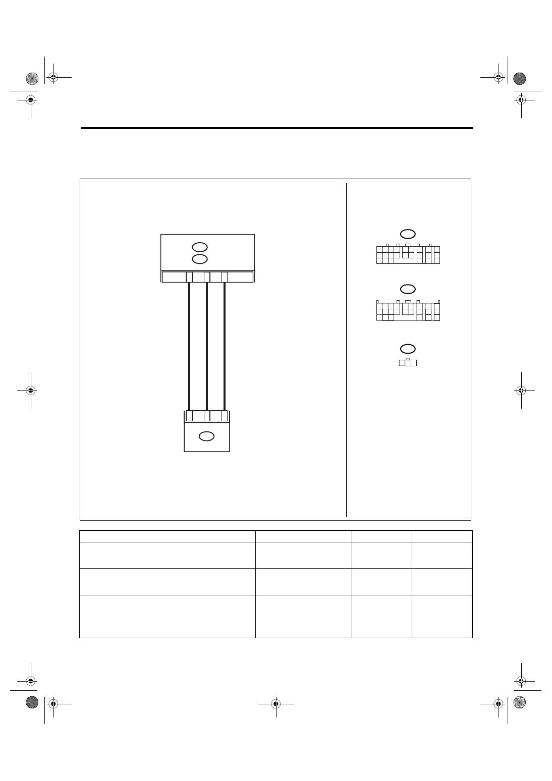
WIRING DIAGRAM:
Step
Check
Yes
No
1
CONFIRM WQUIPMENT OF VEHICLE.
Is VDC equipped with the vehi-
cle? And is there VDC OFF
switch in the instrument panel?
2
CHECK DTC OF TCM.
Is DTC of AT CAN communica-
tion detected?
Perform the diag-
nosis according to
DTC.
3
CHECK DTC OF ABS.
Is DTC of ABS detected?
Perform the diag-
nosis according to
DTC of ABS
Temporary poor
contact occurs.
Recheck the har-
ness and connec-
tor for faulty.
AT-01634
A13
B54
TCM
B359
2
1
3
B5
B6
2 3
1
B54
B359
G SENSOR
1 2 3 4
10 11 12
19 20 21
13
5 6
14 15
7
8
9
16
17
18
22
23
24
B55
A:
B55
B:
1 2
7
8
9
5 6
3 4
10 11 12
19 20 21
13
14 15
16
17
18
22
23
24
A:
B:
5AT(diag)-122
AUTOMATIC TRANSMISSION (DIAGNOSTICS)
Diagnostic Procedure with Diagnostic Trouble Code (DTC)
4
CHECK OUTPUT OF LATERAL G SENSOR
USING SUBARU SELECT MONITOR.
1) Select {Current Data Display & Save} in
Subaru Select Monitor.
2) Read the lateral G sensor output on Subaru
Select Monitor display.
Is the value on display 2.3 —
2.7 V when the lateral G sen-
sor is in horizontal position?
5
CHECK POOR CONTACT IN CONNECTOR. Is there poor contact in con-
nector between TCM and lat-
eral G sensor?
Repair the con-
nector.
6
CHECK ABSCM&H/U.
1) Connect all the connectors.
2) Perform the clear memory mode.
3) Perform the inspection mode.
4) Read the DTC.
Is the same DTC displayed?
Replace the TCM.
<Ref. to 5AT-61,
Transmission Con-
trol Module
(TCM).>
7
CHECK OTHER DTC DETECTION.
Is any other DTC displayed?
Perform the diag-
nosis according to
DTC.
Temporary poor
contact occurs.
8
CHECK CONDITIONAL INFORMATION
WHEN FAULTY.
Read the lateral G sensor output on Subaru
Select Monitor display.
Is the reading on monitor dis-
play 4.65 V or more?
9
CHECK OPEN CIRCUIT IN LATERAL G SEN-
SOR OUTPUT HARNESS AND GROUND
HARNESS.
1) Turn the ignition switch to OFF.
2) Disconnect the connector from TCM.
3) Measure the resistance between TCM con-
nector terminals.
Connector & terminal
(B55) No. 5 — No. 1:
Is the resistance 4.3 — 4.9
k
Ω?
Repair the har-
ness connector
between lateral G
sensor and
ABSCM&H/U.
10
CHECK BATTERY SHORT OF HARNESS.
1) Turn the ignition switch to OFF.
2) Remove the console box.
3) Disconnect the connector from lateral G
sensor.
4) Disconnect the connector from TCM.
5) Measure the voltage between TCM con-
nector and chassis ground.
Connector & terminal
(B55) No. 6 (+) — Chassis ground (
−
):
Is the voltage less than 1 V?
Repair the har-
ness between lat-
eral G sensor and
TCM.
11
CHECK BATTERY SHORT OF HARNESS.
1) Turn the ignition switch to ON.
2) Measure the voltage between TCM con-
nector and chassis ground.
Connector & terminal
(B55) No. 6 (+) — Chassis ground (
−
):
Is the voltage less than 1 V?
Repair the har-
ness between lat-
eral G sensor and
TCM.
12
CHECK POOR CONTACT IN CONNECTOR. Is there poor contact in con-
nector between TCM and lat-
eral G sensor?
Repair the con-
nector.
13
CHECK TCM.
1) Connect all the connectors.
2) Perform the clear memory mode.
3) Perform the inspection mode.
4) Read the DTC.
Is the same DTC displayed?
Replace the TCM.
<Ref. to 5AT-61,
Transmission Con-
trol Module
(TCM).>
14
CHECK OTHER DTC DETECTION.
Is any other DTC displayed?
Perform the diag-
nosis according to
DTC.
Temporary poor
contact occurs.
Step
Check
Yes
No
Нет комментариевНе стесняйтесь поделиться с нами вашим ценным мнением.
Текст