Subaru Legacy IV (2008 year). Service manual — part 906

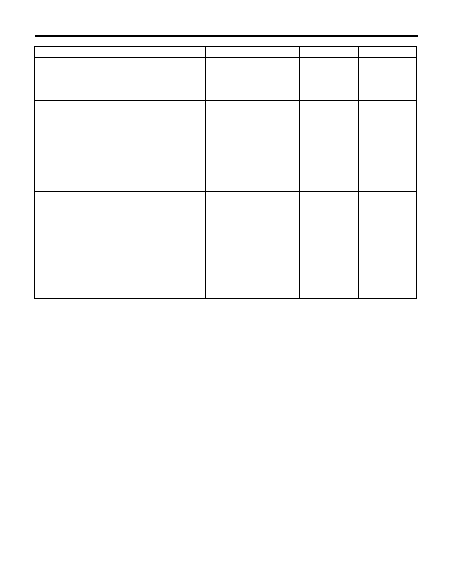
ABS(diag)-23
ABS Warning Light / Brake Warning Light Illumination Pattern
ABS (DIAGNOSTICS)
B: ABS WARNING LIGHT DOES NOT COME ON
DETECTING CONDITION:
• Defective combination meter
• Defective harness
TROUBLE SYMPTOM:
When the ignition switch is turned to ON (engine OFF), ABS warning light does not illuminate.
WIRING DIAGRAM:
MAIN SBF
SBF-6
No.5
No.33
A:
i10
B:
i11
E
E
B301
18
15
22
ABSCM & H/U
A7
8
i3
B38
A3
1 2 3 4 5 6 7 8 9 10 11
16 17 18 19 20 21 22 23 24 25 26
13
12
15
14
i10
2
1
3 4
6 7 8 9 10
22
21
20
19
18
17
16
15
14
13
12
11
5
A:
B301
B38
1
*
20
9
1
*
i11
B:
2
1
3
4 5 6
14
13
12
11
10
9
8
7
ABS01069
1 2 3 4
5 6 7 8 9
10 11 12 13 14 15 16 17 18 19 20
BATTERY
IGNITION
SWITCH
COMBINATION
METER
: NORMAL METER
METER WITH MID
REVERSE
CIRCUIT
REVERSE
CIRCUIT
BRAKE
W
ARNING
LIGHT
ABS
W
ARNING
LIGHT
: A5
: B5
ABS(diag)-24
ABS Warning Light / Brake Warning Light Illumination Pattern
ABS (DIAGNOSTICS)
Step
Check
Yes
No
1
CHECK ILLUMINATION OF OTHER LIGHTS.
Turn the ignition switch to ON. (engine OFF)
Do other warning lights illumi-
nate?
Go to step 2.
Check the combi-
nation meter.
2
READ DTC.
Read the DTC. <Ref. to ABS(diag)-18, Read
Diagnostic Trouble Code (DTC).>
Is DTC displayed?
Perform the diag-
nosis according to
DTC.
Go to step 3.
3
CHECK GROUND SHORT OF HARNESS.
1) Turn the ignition to OFF.
2) Disconnect the connector (B301) from the
ABSCM&H/U.
3) Disconnect the connector (i10) (Model with
the normal meter) or (i11) (Model with the meter
with MID) from the combination meter.
4) Measure the resistance between ABSCM
connector and chassis ground.
Connector & terminal
(B301) No. 22 — Chassis ground:
Is the resistance 1 M
: or
more?
Go to step 4.
Repair harness
and connector
between
ABSCM&H/U and
combination meter.
4
CHECK ABSCM.
1) Connect the connector (B301) to the
ABSCM&H/U.
2) Turn the ignition to ON.
3) Measure the resistance between the combi-
nation meter connector and chassis ground
soon after the ignition switch is turned to ON
(within 1.5 seconds).
Connector & terminal
Model with the normal meter
(i10) No. 5 — Chassis ground:
Model with the meter with MID
(i11) No. 5 — Chassis ground:
Is the resistance 1 M
: or
more?
Check the combi-
nation meter.
Replace the
ABSCM only. <Ref.
to ABS-8,
REPLACEMENT,
ABS Control Mod-
ule and Hydraulic
Control Unit
(ABSCM&H/U).>
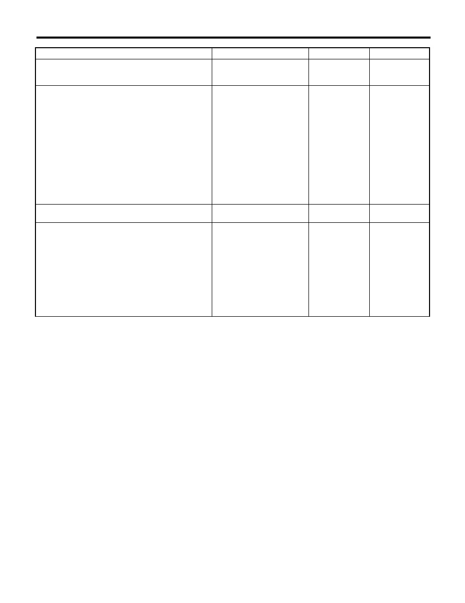
ABS(diag)-25
ABS Warning Light / Brake Warning Light Illumination Pattern
ABS (DIAGNOSTICS)
C: ABS WARNING LIGHT DOES NOT GO OFF
DETECTING CONDITION:
• Defective combination meter
• Open circuit in harness
TROUBLE SYMPTOM:
When starting the engine, the ABS warning light is kept on.
WIRING DIAGRAM:
MAIN SBF
SBF-6
No.5
No.33
A:
i10
B:
i11
E
E
B301
18
15
22
ABSCM & H/U
A7
8
i3
B38
A3
1 2 3 4 5 6 7 8 9 10 11
16 17 18 19 20 21 22 23 24 25 26
13
12
15
14
i10
2
1
3 4
6 7 8 9 10
22
21
20
19
18
17
16
15
14
13
12
11
5
A:
B301
B38
1
*
20
9
1
*
i11
B:
2
1
3
4 5 6
14
13
12
11
10
9
8
7
ABS01069
1 2 3 4
5 6 7 8 9
10 11 12 13 14 15 16 17 18 19 20
BATTERY
IGNITION
SWITCH
COMBINATION
METER
: NORMAL METER
METER WITH MID
REVERSE
CIRCUIT
REVERSE
CIRCUIT
BRAKE
W
ARNING
LIGHT
ABS
W
ARNING
LIGHT
: A5
: B5
ABS(diag)-26
ABS Warning Light / Brake Warning Light Illumination Pattern
ABS (DIAGNOSTICS)
Step
Check
Yes
No
1
READ DTC.
Read the DTC. <Ref. to ABS(diag)-18, Read
Diagnostic Trouble Code (DTC).>
Is DTC displayed?
Perform the diag-
nosis according to
DTC.
Go to step 2.
2
CHECK WIRING HARNESS.
1) Turn the ignition to OFF.
2) Disconnect the connector (B301) from the
ABSCM&H/U.
3) Disconnect the connector (i10) (Model with
the normal meter) or (i11) (Model with the meter
with MID) from the combination meter.
4) Measure the resistance between ABSCM
connector and combination meter connector.
Connector & terminal
Model with the normal meter
(B301) No. 22 — (i10) No. 5:
Model with the meter with MID
(B301) No. 22 — (i11) No. 5:
Is the resistance less than 0.5
:? Go to step 3.
Repair harness
and connector
between
ABSCM&H/U and
combination meter.
3
CHECK POOR CONTACT IN CONNECTOR.
Check for poor contact in all connectors.
Is there poor contact?
Repair the connec-
tor.
Go to step 4.
4
CHECK ABSCM.
1) Connect the connector (B301) to the
ABSCM&H/U.
2) Turn the ignition switch to ON.
3) Measure the resistance between combina-
tion meter connector and chassis ground.
Connector & terminal
Model with the normal meter
(i10) No. 5 — Chassis ground:
Model with the meter with MID
(i11) No. 5 — Chassis ground:
Is the resistance less than 0.5
:? Check the combi-
nation meter.
Replace the
ABSCM only. <Ref.
to ABS-8,
REPLACEMENT,
ABS Control Mod-
ule and Hydraulic
Control Unit
(ABSCM&H/U).>
Нет комментариевНе стесняйтесь поделиться с нами вашим ценным мнением.
Текст