Subaru Legacy IV (2008 year). Service manual — part 907
ABS(diag)-27
ABS Warning Light / Brake Warning Light Illumination Pattern
ABS (DIAGNOSTICS)
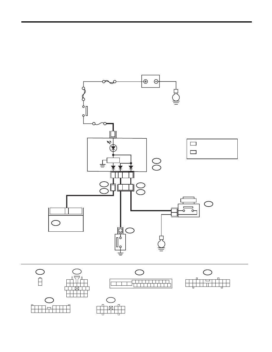
D: BRAKE WARNING LIGHT DOES NOT GO OFF
DETECTING CONDITION:
• Brake warning light circuit is shorted.
• Defective sensor/connector
TROUBLE SYMPTOM:
After starting the engine, the brake warning light remains lit though the parking lever is released.
WIRING DIAGRAM:
B301
B16
1
2
1 2 3 4 5 6 7 8 9 10 11
16 17 18 19 20 21 22 23 24 25 26
13
12
15
14
i10
2
1
3 4
6 7 8 9 10
22
21
20
19
18
17
16
15
14
13
12
11
5
A:
B:
E
MAIN SBF
SBF-6
E
No.5
8
B301
B36
B16
i1
B38
i3
B404
i10
A:
i11
B:
ABSCM & H/U
A3
A7
20
16
15
1
2
1
*
2
*
2
*
B38
1 2 3 4
5 6 7 8 9
10 11 12 13 14 15 16 17 18 19 20
i1
5 6 7 8
2
1
9
4
3
10
24
22
23
25
27
26
28
11 12 13
14 15 16
17 18 19 20 21
ABS01070
1
*
1 2 3
4 5 6
7 8 9 10 11 12 13 14
i11
BATTERY
IGNITION
SWITCH
COMBINATION
METER
PARKING BRAKE
FLUID LEVEL
WARNING LIGHT
BRAKE FLUID
LEVEL SWITCH
PARKING
SWITCH
REVERSE
CIRCUIT
: NORMAL METER
METER WITH MID
: A8
: A4
: NORMAL METER
METER WITH MID
: B10
: A8

ABS(diag)-28
ABS Warning Light / Brake Warning Light Illumination Pattern
ABS (DIAGNOSTICS)
Step
Check
Yes
No
1
CHECK INSTALLATION OF ABSCM&H/U
CONNECTOR.
1) Turn the ignition switch to OFF.
2) Check that the ABSCM&H/U connector is
inserted to ABSCM&H/U until the clamp locks
onto it.
Is the connector firmly
inserted?
Go to step 2.
Insert the
ABSCM&H/U con-
nector until the
clamp locks com-
pletely.
2
READ DTC.
Read the DTC. <Ref. to ABS(diag)-18, Read
Diagnostic Trouble Code (DTC).>
Is DTC displayed?
Perform the diag-
nosis according to
DTC.
Go to step 3.
3
CHECK BRAKE FLUID AMOUNT.
Check the amount of brake fluid in the reservoir
tank of the master cylinder.
Is the amount of brake fluid
between the lines of “MAX” and
“MIN”?
Go to step 4.
Replenish brake
fluid to the speci-
fied value.
4
CHECK BRAKE FLUID LEVEL SWITCH.
1) Disconnect the level switch connector (B16)
from master cylinder.
2) Measure the resistance of master cylinder
terminals.
Terminals
No. 1 — No. 2:
Is the resistance 1 M
: or
more?
Go to step 5.
Replace the mas-
ter cylinder.
5
CHECK PARKING BRAKE SWITCH.
1) Disconnect the connector (B404) from park-
ing brake switch.
2) Release the parking brake.
3) Measure the resistance between parking
brake switch terminal and chassis ground.
Is the resistance 1 M
: or
more?
Go to step 6.
Replace the park-
ing brake switch.
6
CHECK GROUND SHORT OF HARNESS.
1) Disconnect the connectors (i10 and i11)
from the combination meter.
2) Measure the resistance between combina-
tion meter connector and chassis ground.
Connector & terminal
Model with the normal meter
(i10) No. 8 — Chassis ground:
(i11) No. 10 — Chassis ground:
Model with the meter with MID
(i10) No. 8 — Chassis ground:
(i10) No. 4 — Chassis ground:
Is the resistance 1 M
: or
more?
Go to step 7.
Repair the harness
connector between
combination meter
and parking brake
switch.
7
CHECK HARNESS.
1) Disconnect the connector (B301) from the
ABSCM&H/U.
2) Disconnect the connector (i10) from the
combination meter.
3) Measure the resistance between the
ABSCM&H/U connector and combination
meter connector.
Connector & terminal
(B301) No. 8 — (i10) No. 7:
Is the resistance less than 0.5
:? Go to step 8.
Repair the harness
between the
ABSCM&H/U and
the combination
meter.
8
CHECK POOR CONTACT IN CONNECTOR.
Check for poor contact in all connectors.
Is there poor contact?
Repair the connec-
tor.
Go to step 9.
9
CHECK ABSCM.
1) Connect the connector to the ABSCM&H/U.
2) Turn the ignition switch to ON.
3) Measure the resistance between combina-
tion meter connector and chassis ground.
Connector & terminal
(i10) No. 7 — Chassis ground:
Is the resistance less than 0.5
:? Check the combi-
nation meter.
Replace the
ABSCM only. <Ref.
to ABS-8,
REPLACEMENT,
ABS Control Mod-
ule and Hydraulic
Control Unit
(ABSCM&H/U).>

ABS(diag)-29
List of Diagnostic Trouble Code (DTC)
ABS (DIAGNOSTICS)
11.List of Diagnostic Trouble Code (DTC)
A: LIST
DTC
Content of diagnosis
Display
Reference target
C0101
ABS wheel speed sen-
sor malfunction (Bro-
ken wire, short)
Rear ABS wheel
speed sensor RH
Rear Right ABS Sen-
sor Circuit Open or
Shorted Battery
<Ref. to ABS(diag)-31, DTC C0101 ABS WHEEL
SPEED SENSOR MALFUNCTION RR SENSOR
(BROKEN WIRE, INPUT VOLTAGE TOO HIGH),
Diagnostic Procedure with Diagnostic Trouble
Code (DTC).>
C0102
Rear ABS wheel
speed sensor LH
Rear Left ABS Sensor
Circuit Open or
Shorted Battery
<Ref. to ABS(diag)-31, DTC C0102 ABS WHEEL
SPEED SENSOR MALFUNCTION RL SENSOR
(BROKEN WIRE, INPUT VOLTAGE TOO HIGH),
Diagnostic Procedure with Diagnostic Trouble
Code (DTC).>
C0103
Front ABS wheel
speed sensor RH
Front Right ABS Sen-
sor Circuit Open or
Shorted Battery
<Ref. to ABS(diag)-31, DTC C0103 ABS WHEEL
SPEED SENSOR MALFUNCTION FR SENSOR
(BROKEN WIRE, INPUT VOLTAGE TOO HIGH),
Diagnostic Procedure with Diagnostic Trouble
Code (DTC).>
C0104
Front ABS wheel
speed sensor LH
Front Left ABS Sensor
Circuit Open or
Shorted Battery
<Ref. to ABS(diag)-32, DTC C0104 ABS WHEEL
SPEED SENSOR MALFUNCTION FL SENSOR
(BROKEN WIRE, INPUT VOLTAGE TOO HIGH),
Diagnostic Procedure with Diagnostic Trouble
Code (DTC).>
C0105
ABS wheel speed sen-
sor malfunction (ABS
wheel speed sensor
abnormal signal)
Abnormal signal
of rear ABS
wheel speed sen-
sor RH
Rear Right ABS Sen-
sor Signal
<Ref. to ABS(diag)-34, DTC C0105 REAR ABS
WHEEL SPEED SENSOR RH MALFUNCTION
(ABS WHEEL SPEED SENSOR ABNORMAL
SIGNAL), Diagnostic Procedure with Diagnostic
Trouble Code (DTC).>
C0106
Abnormal signal
of rear ABS
wheel speed sen-
sor LH
Rear Left ABS Sensor
Signal
<Ref. to ABS(diag)-34, DTC C0106 REAR ABS
WHEEL SPEED SENSOR LH MALFUNCTION
(ABS WHEEL SPEED SENSOR ABNORMAL
SIGNAL), Diagnostic Procedure with Diagnostic
Trouble Code (DTC).>
C0107
Abnormal signal
of front ABS
wheel speed sen-
sor RH
Front Right ABS Sen-
sor Signal
<Ref. to ABS(diag)-34, DTC C0107 FRONT ABS
WHEEL SPEED SENSOR RH MALFUNCTION
(ABS WHEEL SPEED SENSOR ABNORMAL
SIGNAL), Diagnostic Procedure with Diagnostic
Trouble Code (DTC).>
C0108
Abnormal signal
of front ABS
wheel speed sen-
sor LH
Front Left ABS Sensor
Signal
<Ref. to ABS(diag)-35, DTC C0108 FRONT ABS
WHEEL SPEED SENSOR LH MALFUNCTION
(ABS WHEEL SPEED SENSOR ABNORMAL
SIGNAL), Diagnostic Procedure with Diagnostic
Trouble Code (DTC).>
C0109
Power voltage malfunction
Power Supply Voltage
Failure
<Ref. to ABS(diag)-47, DTC C0109 POWER
VOLTAGE MALFUNCTION, Diagnostic Proce-
dure with Diagnostic Trouble Code (DTC).>
C0110
ABS control module malfunction
Electrical Control Mod-
ule
<Ref. to ABS(diag)-45, DTC C0110 ABS CON-
TROL MODULE MALFUNCTION, Diagnostic
Procedure with Diagnostic Trouble Code (DTC).>
C0111
Motor/motor relay on failure
Motor and Motor Relay
<Ref. to ABS(diag)-52, DTC C0111 MOTOR/
MOTOR RELAY MALFUNCTION, Diagnostic
Procedure with Diagnostic Trouble Code (DTC).>
C0114
Defective valve relay
Valve Relay
<Ref. to ABS(diag)-50, DTC C0114 VALVE
RELAY MALFUNCTION, Diagnostic Procedure
with Diagnostic Trouble Code (DTC).>

ABS(diag)-30
List of Diagnostic Trouble Code (DTC)
ABS (DIAGNOSTICS)
C0115
ABS wheel speed sen-
sor malfunction (ABS
wheel speed sensor
abnormal signal)
Abnormal ABS
wheel speed sen-
sor on any one of
four sensors
Any One of Four ABS
Sensors Signal
<Ref. to ABS(diag)-38, DTC C0115 ABS WHEEL
SPEED SENSOR SIGNAL MALFUNCTION IN
ONE OF FOUR WHEELS, Diagnostic Procedure
with Diagnostic Trouble Code (DTC).>
C0116
Stop light switch circuit malfunction
Brake Light Switch
<Ref. to ABS(diag)-54, DTC C0116 FAULTY
STOP LIGHT SWITCH, Diagnostic Procedure
with Diagnostic Trouble Code (DTC).>
C0118
Faulty G sensor output voltage
G Sensor Failure
<Ref. to ABS(diag)-56, DTC C0118 G SENSOR
OUTPUT VOLTAGE MALFUNCTION, Diagnostic
Procedure with Diagnostic Trouble Code (DTC).>
C0119
Abnormal G sensor output signal
G Sensor Signal
<Ref. to ABS(diag)-59, DTC C0119 G SENSOR
OUTPUT SIGNAL MALFUNCTION, Diagnostic
Procedure with Diagnostic Trouble Code (DTC).>
C0120
Inlet valve malfunction
in hydraulic unit
Front inlet valve
LH
FL Hold Valve mal-
function
<Ref. to ABS(diag)-40, DTC C0120 FRONT
INLET SOLENOID VALVE LH MALFUNCTION IN
ABS CONTROL MODULE AND HYDRAULIC
CONTROL UNIT (ABSCM&H/U), Diagnostic Pro-
cedure with Diagnostic Trouble Code (DTC).>
C0121
Outlet valve malfunc-
tion in hydraulic unit
Front outlet valve
LH
FL Pressure Reducing
Valve malfunction
<Ref. to ABS(diag)-42, DTC C0121 FRONT
OUTLET SOLENOID VALVE LH MALFUNCTION
IN ABS CONTROL MODULE AND HYDRAULIC
CONTROL UNIT (ABSCM&H/U), Diagnostic Pro-
cedure with Diagnostic Trouble Code (DTC).>
C0122
Inlet valve malfunction
in hydraulic unit
Front inlet valve
RH
FR Hold Valve mal-
function
<Ref. to ABS(diag)-40, DTC C0122 FRONT
INLET SOLENOID VALVE RH MALFUNCTION
IN ABS CONTROL MODULE AND HYDRAULIC
CONTROL UNIT (ABSCM&H/U), Diagnostic Pro-
cedure with Diagnostic Trouble Code (DTC).>
C0123
Outlet valve malfunc-
tion in hydraulic unit
Front outlet valve
RH
FR Pressure Reducing
Valve malfunction
<Ref. to ABS(diag)-42, DTC C0123 FRONT
OUTLET SOLENOID VALVE RH MALFUNCTION
IN ABS CONTROL MODULE AND HYDRAULIC
CONTROL UNIT (ABSCM&H/U), Diagnostic Pro-
cedure with Diagnostic Trouble Code (DTC).>
C0124
Inlet valve malfunction
in hydraulic unit
Rear inlet valve
LH
RL Hold Valve mal-
function
<Ref. to ABS(diag)-40, DTC C0124 REAR INLET
SOLENOID VALVE LH MALFUNCTION IN ABS
CONTROL MODULE AND HYDRAULIC CON-
TROL UNIT (ABSCM&H/U), Diagnostic Proce-
dure with Diagnostic Trouble Code (DTC).>
C0125
Outlet valve malfunc-
tion in hydraulic unit
Rear outlet valve
LH
RL Pressure Reduc-
ing Valve malfunction
<Ref. to ABS(diag)-42, DTC C0125 REAR OUT-
LET SOLENOID VALVE LH MALFUNCTION IN
ABS CONTROL MODULE AND HYDRAULIC
CONTROL UNIT (ABSCM&H/U), Diagnostic Pro-
cedure with Diagnostic Trouble Code (DTC).>
C0126
Inlet valve malfunction
in hydraulic unit
Rear inlet valve
RH
RR Hold Valve mal-
function
<Ref. to ABS(diag)-41, DTC C0126 REAR INLET
SOLENOID VALVE RH MALFUNCTION IN ABS
CONTROL MODULE AND HYDRAULIC CON-
TROL UNIT (ABSCM&H/U), Diagnostic Proce-
dure with Diagnostic Trouble Code (DTC).>
C0127
Outlet valve malfunc-
tion in hydraulic unit
Rear outlet valve
RH
RR Pressure Reduc-
ing Valve malfunction
<Ref. to ABS(diag)-43, DTC C0127 REAR OUT-
LET SOLENOID VALVE RH MALFUNCTION IN
ABS CONTROL MODULE AND HYDRAULIC
CONTROL UNIT (ABSCM&H/U), Diagnostic Pro-
cedure with Diagnostic Trouble Code (DTC).>
C0140
Defective CAN communication
Improper CAN com-
munication
<Ref. to ABS(diag)-49, DTC C0140 CAN COM-
MUNICATION MALFUNCTION, Diagnostic Pro-
cedure with Diagnostic Trouble Code (DTC).>
DTC
Content of diagnosis
Display
Reference target
Нет комментариевНе стесняйтесь поделиться с нами вашим ценным мнением.
Текст