Subaru Legacy IV (2008 year). Service manual — part 989
AC(diag)-8
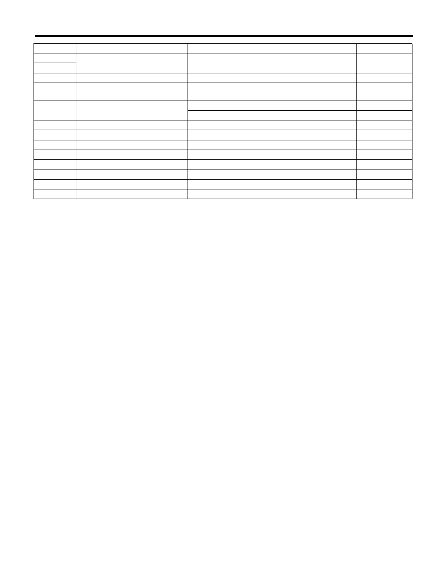
Auto A/C Control Module I/O Signal
HVAC SYSTEM (AUTO A/C) (DIAGNOSTICS)
*1: Battery voltage cannot be measured because of digital signal.
B: WIRING DIAGRAM
1. AIR CONDITIONER AUTO A/C MODEL
<Ref. to WI-111, WIRING DIAGRAM, Air Conditioning System.>
20
Intake door actuator drive signal
When intake door actuator is operating
0.7 V or less
40
21
Ignition power supply
Ignition switch: ON
Battery voltage
22
Pressure switch signal
Ignition switch: ON
Normal: ON
Abnormal: OFF
24
Air mix door actuator (driver’s side)
position signal
Air mix door: Maximum cool position
4 V
Air mix door: Maximum hot position
1 V
25
After-evaporator sensor signal
Changes by the temperature after the evaporator
1 — 4.5 V
26
VER switching signal (FOOT switch)
When switching FOOT
0 V
27
Sensor ground
Always
0 V
28
Control module ground
Always
0 V
32
Heater main relay drive signal
Ignition switch: ON
Battery voltage
33
RAM monitor ON signal
RAM monitor ON
0 V
34
Heater control panel communication
—
*1
35
Heater control panel communication
—
*1
Terminal No.
Remarks
Measuring condition
Standard
AC(diag)-9
Diagnostic Chart for Self-Diagnosis
HVAC SYSTEM (AUTO A/C) (DIAGNOSTICS)
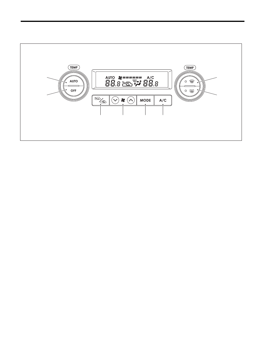
5. Diagnostic Chart for Self-Diagnosis
A: OPERATION
NOTE:
For A/C system self-diagnosis, there is one that checks the control panel, and the other that checks the whole
control system (sensor, actuator, blower motor, etc.). Perform the self-diagnosis for control panel first, and
then perform the self-diagnosis for control system.
(1)
Front defroster switch
(4)
Air flow control switch
(7)
FRESH/RECIRC switch
(2)
Rear window defogger switch
(5)
FAN switch
(8)
OFF switch
(3)
A/C switch
(6)
AUTO switch
(8)
(7)
(6)
(4)
(5)
(1)
(2)
(3)
AC-01536
AC(diag)-10
Diagnostic Chart for Self-Diagnosis
HVAC SYSTEM (AUTO A/C) (DIAGNOSTICS)
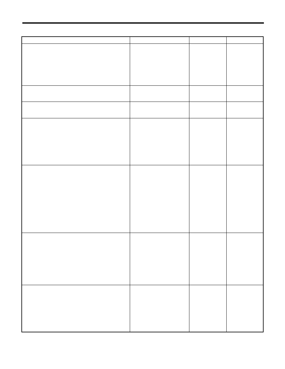
1. A/C CONTROL PANEL SELF-DIAGNOSIS
Step
Check
Yes
No
1
PERFORM A/C CONTROL PANEL SELF-DI-
AGNOSIS FUNCTION.
1) Turn the ignition switch to OFF.
2) Turn the ignition switch to ON with the AUTO
switch and MODE switch pressed at the same
time.
3) All the screen display illuminate (for approx.
5 seconds) and the self-diagnosis mode starts.
Does the self-diagnosis func-
tion operate?
Go to step 2.
<Ref. to AC(diag)-
14, A/C OR SELF-
DIAGNOSIS SYS-
TEMS DO NOT
OPERATE, Diag-
nostics for A/C
System Malfunc-
tion.>
2
CHECK SCREEN DISPLAY.
Check the illumination condition while the dis-
play is illuminated.
Does all the screen display and
indicators illuminate?
Go to step 3.
Replace the A/C
control panel.
3
CHECK SCREEN DISPLAY.
After the illumination ends, check the display.
Are the numbers 11 — 14 dis-
played at the setting tempera-
ture display area?
Go to step 5.
Go to step 4.
4
CHECK SWITCH AND TEMPERATURE CON-
TROL DIAL INPUT.
1) Operate each switch or dial according to the
switch check table.
2) Check the display or indicator illumination
condition when operating the switch or dial.
<Ref. to AC(diag)-11, SWITCH CHECK TABLE,
OPERATION, Diagnostic Chart for Self-Diagno-
sis.>
Does the input of each switch or
dial correspond to the switch
check list?
Go to step 5.
Replace the heater
control panel.
5
CHECK A/C CONTROL PANEL COMMUNI-
CATION.
1) Turn the ignition switch to OFF.
2) Disconnect the connector of the auto A/C
control module.
3) Using a suitable lead wire, short the termi-
nal No. 34 and No. 35 of auto A/C control mod-
ule vehicle side connector (B282).
4) Turn the ignition switch to ON with the A/C
switch and AUTO switch pressed at the same
time.
5) Check the screen display when operating
each switch and dial.
Is “CL” displayed on the screen
when operating each switch
and dial?
Go to step 6.
Go to step 7.
6
CHECK A/C CONTROL PANEL COMMUNI-
CATION.
1) Turn the ignition switch to OFF.
2) Disconnect the lead wire used to short the
terminals.
3) Turn the ignition switch to ON with the A/C
switch and AUTO switch pressed at the same
time.
4) Check the screen display when operating
each switch and dial.
Is “OP” displayed on the screen
when operating each switch
and dial?
A/C control panel
and body harness
are normal.
Go to step 7.
7
CHECK HARNESS.
1) Turn the ignition switch to OFF.
2) Disconnect the A/C control panel connector
(i88).
3) Measure the resistance between connec-
tors with a tester.
Connector & terminal
(i88) No. 7 — (B282) No. 34:
(i88) No. 3 — (B282) No. 35:
Is the resistance less than 10
:? Go to step 8.
Repair the open
circuit of the har-
ness between A/C
control panel and
auto A/C control
module.
AC(diag)-11
Diagnostic Chart for Self-Diagnosis
HVAC SYSTEM (AUTO A/C) (DIAGNOSTICS)
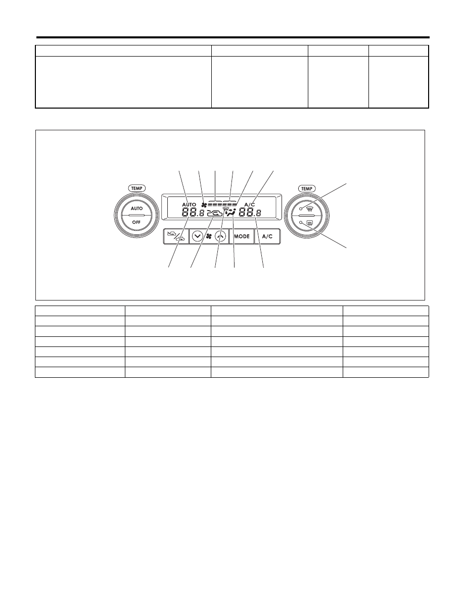
2. SWITCH CHECK TABLE
8
CHECK HARNESS.
Measure the resistance between connectors
with a tester.
Connector & terminal
(i88) No. 7 — No. 3:
Is the resistance less than 10
:?
Repair the short
circuit of the har-
ness between A/C
control panel and
auto A/C control
module.
Replace the A/C
control panel.
Switch
Display screen
Switch
Display screen
A/C switch
(6)
FAN switch (+)
(4)
AUTO switch
(1)
FAN switch (–)
(3)
Air flow control switch
(9)
Driver’s side temperature control dial
(9), (10), (12)
FRESH/RECIRC
(13)
Passenger’s side temperature control dial
(9), (11), (12)
Defroster switch
(7), (12)
OFF switch
(2), (5)
Rear defogger switch
(8)
Step
Check
Yes
No
(11)
(4)
(5)
(6)
(3)
(2)
(1)
(10)
(9)
(12)
(13)
(7)
(8)
AC-01684
Нет комментариевНе стесняйтесь поделиться с нами вашим ценным мнением.
Текст